
1. Core Technical Overview: Power Conversion in Hydraulic Drivetrains
In the demanding landscape of modern mechanization, the integration of hydraulic motors with mechanical power transmission dictates the operational limits of field equipment. The agricultural gearbox designed specifically for hydraulic drive applications acts as the critical interface between high-pressure fluid dynamics and sheer mechanical torque. These gear drives are engineered to capture the rotational energy generated by hydraulic motors—often characterized by variable high speeds and lower torques—and geometrically multiply this torque to drive heavy-duty implements such as augers, conveyors, rotary cutters, and feed mixers.
Unlike standard PTO-driven systems, hydraulic drive gearboxes must accommodate severe radial and axial loads exerted by hydraulic motor mounting splines, alongside the rapid start-stop-reverse cycles typical of hydraulic circuitry. GBC (General Bearing Company Pty Ltd.), acting as the exclusive EVER-POWER Group Australia Agency, has systematically deployed these advanced transmission units across the vast and unforgiving terrains of Australia, ensuring continuous operation where conventional linear drivetrains fail.

2. Comprehensive Technical Specifications & Parameter Capabilities
The engineering envelope of our hydraulic drive transmission units is defined by stringent metallurgical standards and precision machining. Below are 30 critical parameters detailing the baseline capabilities and customization ranges of our drivetrain solutions.
| # | Technical Parameter | Value / Range | Standard / Protocol |
|---|---|---|---|
| 1 | Continuous Torque Capacity | 1,200 Nm – 18,500 Nm | AGMA 6013-A06 |
| 2 | Peak Overload Torque | Up to 2.5x Continuous Torque | ISO 6336 |
| 3 | Gear Ratio Range | 1:1.25 to 1:65.4 | Customizable Geometry |
| 4 | Input Speed (Max) | 3,600 RPM | Hydraulic Motor Specific |
| 5 | Input Interface | SAE A, B, C, D Splines / Keyed | ANSI B92.1 |
| 6 | Output Shaft Configuration | Solid, Hollow Splined, Flange | DIN 5480 / ISO 14 |
| 7 | Housing Material | Nodular Cast Iron QT450-10 | ASTM A536 |
| 8 | Gear Material | 20CrMnTi Forged Alloy | EN 10084 |
| 9 | Heat Treatment Depth | Carburized 0.8mm – 1.2mm | Hardness HRC 58-62 |
| 10 | Lubrication Type | Oil Splash / Pressurized Circulation | EP 80W-90 / ISO VG 220 |
| 11 | Ingress Protection Rating | IP67 / IP68 (Submersible option) | IEC 60529 |
| 12 | Operating Temperature | -40°C to +115°C | Ambient & Internal Monitor |
| 13 | Bearing Systems | Tapered Roller / Spherical Roller | ISO 281 |
| 14 | Fatigue Life (L10) | > 15,000 Hours at Rated Load | ABMA Standards |
| 15 | Sealing Technology | Double-Lip FKM (Viton) Oil Seals | DIN 3760 |
| 16 | Vibration Threshold | < 4.5 mm/s (RMS) | ISO 10816-3 |
| 17 | Noise Emission Level | < 78 dB(A) at 1500 RPM | ISO 3744 |
| 18 | Mechanical Efficiency | 94% – 97.5% per stage | Thermal Rated |
| 19 | Paint & Coating | Epoxy Primer + Polyurethane Topcoat | ISO 12944 (C4 Category) |
| 20 | Salt Spray Resistance | 720 Hours Minimum | ASTM B117 |
| 21 | Radial Load Capacity | Up to 45,000 N | Output Shaft specific |
| 22 | Axial Load Capacity | Up to 28,000 N | With integrated thrust bearings |
| 23 | Breather System | Sintered Bronze / Desiccant Breather | 3 Micron Filtration |
| 24 | Backlash Clearance | 8 – 15 Arcmin | Precision Ground Gears |
| 25 | Dry Weight | 25 kg – 350 kg | Depending on model |
| 26 | Thermal Dissipation | Finned Housing / Optional Coolers | At 40°C Ambient |
| 27 | Overload Protection | Shear Pin / Slip Clutch Integrations | Adjustable Torque Limiter |
| 28 | Mounting Positions | Universal (M1 to M6) | Oil level plugs adjusted |
| 29 | Gear Tooth Profile | Involute Helical / Spiral Bevel | Klingelnberg / Gleason |
| 30 | Traceability | Laser Engraved QR & Serializing | ISO 9001:2015 |
3. Working Principle & Architecture in Hydraulic Ecosystems
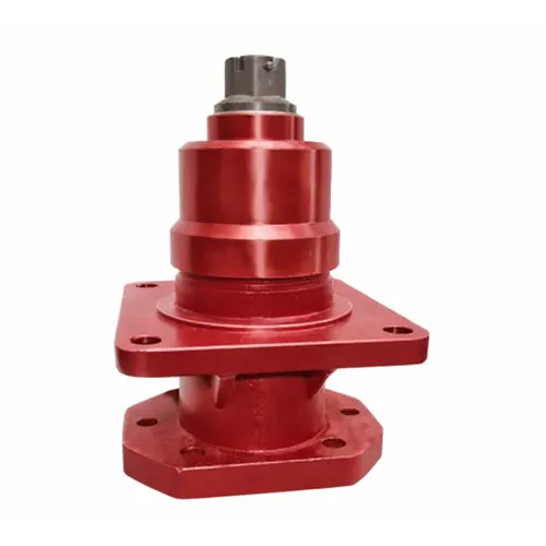
The structural physiology of a hydraulic drive gearbox revolves around its role as a kinetic translator. Situated directly between the hydraulic gerotor/piston motor and the final drive element (such as a conveyor drum or mixing auger), the gearbox eliminates the need for complex, vulnerable mechanical drivelines spanning the length of the tractor or implement.
Functional Architecture: The hydraulic fluid pumped from the tractor enters the hydraulic motor, creating rotational force on the motor’s output shaft. This shaft is directly coupled—often via an SAE splined internal sleeve—to the primary input gear of our agricultural gearbox. Through a series of precision-cut helical or spiral bevel gears, the high-velocity rotation (e.g., 2000 RPM) is reduced to a usable, high-torque output (e.g., 50 RPM). The heavy-duty output bearings of the gearbox simultaneously absorb the tremendous physical loads exerted by the implement, isolating the sensitive hydraulic motor seals from premature failure caused by radial deflection.
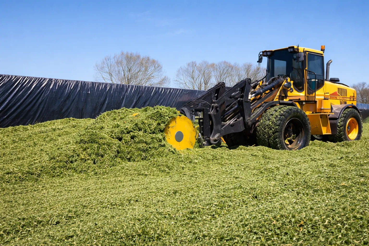
4. New South Wales & Queensland Extreme Operating Conditions Field Study
Operating hydraulic systems in Australia poses unique thermal and mechanical challenges. From the sugarcane fields of Queensland (QLD) to the vast wheat belts of New South Wales (NSW) and Victoria (VIC), equipment is routinely subjected to ambient temperatures exceeding 45°C during summer harvests, compounded by the abrasive ingress of fine red dust (Latossolo equivalents).
Thermal Expansion & Viscosity Breakdown: Hydraulic fluid inherently generates heat under pressure. When the hydraulic motor transfers this heat directly to the gearbox housing via conduction, standard gear oils can undergo sheer thinning. EVER-POWER gearboxes combat this by utilizing a +30% increased cooling fin surface area and utilizing high-viscosity index synthetic lubricants, maintaining an internal operating temperature safely below 90°C even during non-stop 12-hour shifts in the outback.
Shock Load Resistance: In environments like the rocky terrains of Perth (WA) or deep ripping operations in Adelaide (SA), submerged obstacles cause sudden, violent decelerations. Our drivetrain systems incorporate 20CrMnTiH alloy steel with a heavily carburized surface and a highly ductile core, engineered to absorb shock waves that would typically cause shear fractures in standard output shafts.
5. Drivetrain Systems Compatibility & Brand Replacement Matrices
Equipment downtime during peak agricultural windows in Australia costs thousands of dollars per hour. To facilitate rapid MRO (Maintenance, Repair, and Operations) decisions, our engineered solutions feature standardized mounting flanges, shaft dimensions, and volumetric profiles that serve as drop-in replacements for major European and North American OEM components.
Direct Replacement Capabilities:
- Comer Industries®: Series PGA, PGW, and planetary hydraulic drives.
- Bondioli & Pavesi®: Series S100 to S300 hydraulic motor interfaces.
- Brevi Planetary®: Compact hydraulic drives for mixing wagons.
- Walterscheid®: Direct coupled hydraulic gearboxes.
*Legal Disclaimer: All manufacturer names, symbols, and descriptions (such as Comer®, Bondioli & Pavesi®, etc.) are used for reference and identification purposes only. Our systems are engineered by EVER-POWER as aftermarket and OEM alternatives. We do not claim an affiliation with these specific original equipment manufacturers.
6. Australia National Standards & Certification Landscape for Drivetrain Components
Compliance is non-negotiable for machinery distributed by GBC across Australia and neighboring Oceania markets. Engineering an agricultural gearbox requires adherence to rigorous safety and environmental directives.
- AS/NZS 4024 (Safety of Machinery): Mandates that any rotational power transmission, including the input shafts from hydraulic motors, must have fail-safe overload protections and secure shielding. Our gearboxes integrate seamlessly with compliant guarding.
- CE Machinery Directive (2006/42/EC): While European, this standard is heavily referenced by Australian WorkSafe authorities. Our units carry CE compliance, ensuring they meet rigorous international safety protocols regarding noise emissions and structural integrity.
- Crop-Specific Demands: In the winter wheat harvest of Victoria and New South Wales, machinery requires rapid hydraulic actuation for header adjustments. Our systems provide the low-backlash precision necessary for these split-second positional changes without drivetrain slop.
7. The Engineer’s Perspective: Design Philosophy & Field Iteration
“When we redesigned the SAE B-mount hydraulic gearbox series for the Australian market, our primary focus shifted from simple torque transmission to absolute fluid isolation.”
Design Philosophy: We observed that 60% of hydraulic motor failures on agricultural implements were not due to the motor itself, but rather contaminated gear oil from the gearbox bypassing the seal and entering the hydraulic loop. We engineered an intermediate weep-hole cavity with dual directional FKM Viton seals. If either the hydraulic motor seal or the gearbox input seal fails, the fluid drains externally, providing a visual cue to the operator before catastrophic cross-contamination occurs.
Innovation in Metallurgy: Moving away from standard cast housings, our new generation utilizes a proprietary nodular iron blend that offers 18% higher tensile strength. This prevents the housing from micro-flexing under high-pressure hydraulic stalls, keeping the internal gear mesh perfectly aligned.

8. Engineer Field Notes: 5 Real-World Australian Application Cases
Case 1: Sydney (NSW) – Forestry Mulcher Hydraulic Overload
Client Pain Point: “Our hydraulic mulcher heads were snapping input shafts when hitting hidden ironbark stumps, destroying both the gearbox and the $3,000 hydraulic motor.”
EVER-POWER Solution: We installed our heavy-duty series with an integrated mechanical slip clutch tuned exactly to 10% below the motor’s destruction threshold.
Feedback: “Since the retrofit 14 months ago, we’ve had zero shaft shearing. The clutch slips, the operator reverses, and we keep working.”
Case 2: Melbourne (VIC) – Grape Harvester Conveyor Synchronization
Client Pain Point: Vineyards required precise, synchronized speed control of dual conveyors to prevent fruit damage, but existing gearboxes suffered from severe backlash.
EVER-POWER Solution: Deployed precision-ground helical gear units with a strict <10 arcmin backlash tolerance, directly flanged to Danfoss orbital motors.
Feedback: “The smooth transmission of power eliminated the ‘jerking’ motion on the belts, improving our A-grade fruit yield by 8%.”
Case 3: Brisbane (QLD) – Sugarcane Billet Planter
Client Pain Point: Operating in 40°C humidity, the hydraulic gear drives on the planting drums were boiling the internal gear oil, leading to seal pop-outs.
EVER-POWER Solution: Upgraded to housings with maximum thermal fins and swapped the standard breather for a pressure-compensating expansion chamber.
Feedback: “Temperatures dropped by 25°C on the casing. We haven’t blown a seal all season.”
Case 4: Adelaide (SA) – Broadacre Air Seeder Fan Drive
Client Pain Point: The hydraulic motors directly driving the heavy air seeder fans were wearing out their internal bearings due to gyroscopic radial loads on turns.
EVER-POWER Solution: Implemented a 1:1 ratio overhung load adapter (a specialized zero-reduction gearbox) that takes 100% of the radial load onto massive tapered roller bearings, isolating the motor.
Feedback: “Motor lifespan increased from 1 season to 4 seasons. Incredible ROI.”
Case 5: Perth (WA) – Deep Ripper Hydraulic Depth Adjustment
Client Pain Point: The high static holding torque required to maintain ripper depth in hardpan clay was causing premature gear pitting.
EVER-POWER Solution: Transitioned from standard spur gears to a high-contact-ratio worm gear arrangement that provides self-locking characteristics and immense holding torque.
Feedback: “The depth stays exactly where we set it, no hydraulic drift, no gear noise.”
9. Drivetrain Component Selection Guide & Parameter Matrix
Correct sizing prevents 90% of field failures. Use this parameter identification matrix prior to contacting our engineering team at GBC.
| Step | Parameter to Identify | Engineering Consideration for Australia |
|---|---|---|
| 1 | Hydraulic Motor Specs | Identify Displacement (cc/rev), Max Pressure (Bar), Max Flow (L/min). This determines maximum input RPM and Torque. |
| 2 | Target Implement Speed | Required Output RPM. Dictates the exact gear ratio needed (e.g., Input 1500 RPM / Output 300 RPM = 5:1 ratio). |
| 3 | Mounting Interface | SAE A (2-bolt), SAE B, SAE C. Spline count (e.g., 14T 12/24 DP). Ensure absolute match to avoid shaft fretting. |
| 4 | Load Characteristics | Is it uniform (conveyor), moderate shock (mixer), or heavy shock (mulcher)? Drives the Service Factor multiplier (1.0 to 2.5). |
10. Diagnostic Protocols: 10 Troubleshooting Scenarios
Click to expand diagnostic procedures for common field anomalies encountered during severe operational duties.
1. Excessive Housing Temperature (>95°C)
Cause: Overfilling of lubricant causing fluid churning, or hydraulic motor transferring excessive heat. Action: Verify oil level via sight glass; check hydraulic system for pressure relief valve bypass causing heat.
2. Foaming Lubricant exiting the Breather
Cause: Water contamination or incorrect oil viscosity. Action: Drain fluid, flush housing, and refill with specified ISO VG gear oil.
3. High-Pitched Whining Noise
Cause: Input bearing pre-load loss or gear tooth surface wear (micro-pitting). Action: Conduct vibration spectrum analysis; prepare for bearing replacement.
4. Rhythmic Clunking under Load
Cause: Broken gear tooth or severely worn splines on the hydraulic motor input. Action: Immediate shutdown to prevent catastrophic lockup. Remove motor and inspect input splines.
5. Oil Leakage at Input Flange
Cause: Hydraulic motor shaft seal failure pumping hydraulic fluid into the gearbox, over-pressurizing it. Action: Check hydraulic motor seals; check intermediate weep hole.
6. Output Shaft Lateral Play
Cause: Excessive radial load beyond design spec destroying tapered roller bearings. Action: Replace bearings, redesign implement coupling to reduce side-loading.
7. Rust/Corrosion on Internal Gears
Cause: Extended storage without protective oil coating, leading to condensation. Action: Polish gears if surface level; replace if pitting is deep. Always use vapor phase inhibitors during off-season.
8. Difficulty Assembling Hydraulic Motor
Cause: Spline mismatch (e.g., 13 tooth vs 14 tooth) or burrs on the shaft. Action: Never force the fit. Verify spline specs and deburr shaft edges.
9. Paint Blistering on Housing
Cause: Localized extreme heat spots due to localized bearing failure or insufficient lubrication splash. Action: Verify oil level; inspect via end cover.
10. Input Flange Bolt Shearing
Cause: Severe frame flex of the implement transferring twisting forces to the rigid motor-gearbox assembly. Action: Upgrade to Grade 8/10.9 bolts and evaluate implement chassis rigidity.
11. Critical Warning Signs: When to Replace the Transmission Unit
Proactive replacement prevents collateral damage to expensive hydraulic motors and implement structures. Our engineers recommend immediate replacement if you observe:
- Metal Flakes in Oil Analysis: Large brass or steel fragments indicate terminal bearing cage collapse or gear tooth spalling.
- Uncorrectable Backlash: When rotational play at the output shaft exceeds 5 degrees, the gear mesh geometry has fundamentally altered, risking sudden tooth shear.
- Housing Micro-Cracks: Hairline fractures near the mounting flanges, often visible only when oil seeps through them, indicate severe fatigue failure.
12. Industry Dynamics & Australian Agricultural Trends
The drive towards precision agriculture in Australia relies heavily on the electrification and hydraulic control of machinery. Recent reports from the Australian Bureau of Agricultural and Resource Economics and Sciences (ABARES) highlight a 12% year-over-year increase in the adoption of variable-rate hydraulic implements. As tractors supply higher hydraulic flow rates (exceeding 200 L/min), the demand for robust, high-capacity agricultural gearboxes capable of managing these immense kinetic energies has surged. Our localized testing in NSW and QLD ensures our products are ahead of this hydraulic curve.
13. Frequently Asked Questions (FAQ)
1. Can I run a gear motor directly without this gearbox?
While possible for very light loads, hydraulic motors are highly susceptible to radial and axial shaft loads. The gearbox acts as a crucial mechanical buffer, absorbing these destructive forces and multiplying the torque efficiently.
2. What oil viscosity is recommended for Australian summers?
For ambient temperatures consistently above 35°C (like in Western Australia or QLD), we mandate synthetic ISO VG 220 or EP 85W-140 gear oil to maintain film thickness under extreme heat.
3. Are your mounting patterns compatible with Eaton or Danfoss motors?
Yes. Our input flanges are machined to exact SAE standards (SAE A, B, C, D) which are the universal mounting protocols used by Danfoss, Eaton, Parker, and Char-Lynn.
4. How often should the gear oil be changed?
We recommend an initial break-in flush at 50 hours to remove any machining particulates, followed by routine changes every 500 operating hours or annually before the harvest season.
5. Do you stock spare parts in Australia?
Absolutely. GBC maintains extensive warehousing in Sydney, Melbourne, and Brisbane, ensuring rapid dispatch of replacement seals, bearings, and complete gearsets.
6. What happens if the implement hits an immovable object?
Depending on the configuration, hydraulic relief valves on the tractor should bypass the fluid. However, for rotational inertia protection, we can integrate mechanical shear pins or friction slip clutches on the output shaft.
7. Can the gearbox operate vertically?
Yes, but the oil level plugs, breathers, and bearing lubrication methods must be modified for vertical (V1/V3) mounting to ensure top bearings are not starved of oil.
8. How do you handle warranty claims?
Our field engineers at GBC review failure data (oil samples, operational telemetry) to determine root cause. Genuine manufacturing defects are replaced rapidly to minimize your downtime.
14. Comprehensive System Integration: Related Power Transmission Components
At EVER-POWER and GBC, we understand that a gearbox does not operate in isolation. We provide a complete, one-stop ecosystem of agricultural mechanical components engineered to interface flawlessly.
PTO Shafts
For hybrid implements utilizing both hydraulic and mechanical power, our premium PTO shafts feature CE-compliant safety shields, heavy-duty universal joints, and wide-angle constant velocity (CV) joints for tight turning radiuses.
Agricultural Chains & Sprockets
High-tensile roller chains and precision-cut sprockets perfectly matched to the output speeds of our gearboxes, ensuring zero slipping on heavy conveyor and elevator drives.
Pulleys & Belts
Cast iron V-belt pulleys dynamically balanced to eliminate vibration at high input speeds, commonly used alongside hydraulic drives on fan and blower systems.
15. Partner with GBC: Your Complete Drivetrain Authority in Australia
GBC (General Bearing Company Pty Ltd.), acting as the EVER-POWER Group Australia Agency, delivers not just standard components, but custom-engineered mechanical solutions. Whether you are an OEM designing the next generation of hydraulic implements, or a massive agricultural syndicate requiring robust MRO parts, we have the manufacturing scale and engineering depth to support you.
We manufacture a full spectrum of agricultural gearboxes and all associated mechanical accessories. Have a unique hydraulic drive requirement? Send us your blueprints or field constraints, and our metallurgical engineers will design a non-standard custom unit built specifically for your application.