
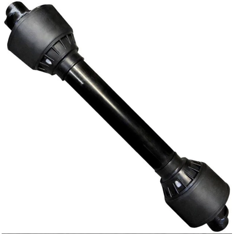
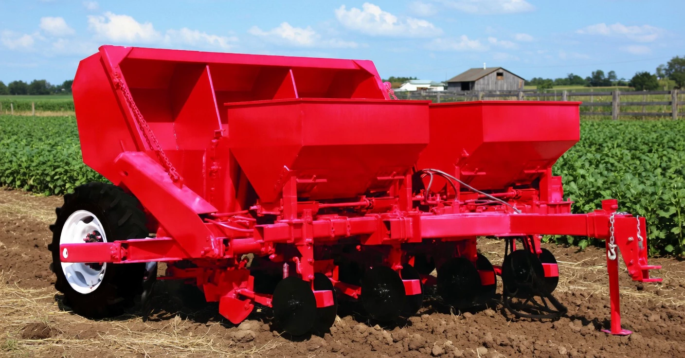
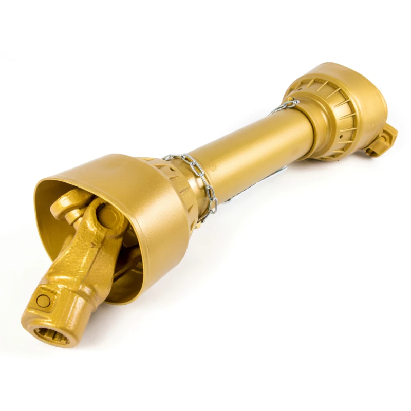
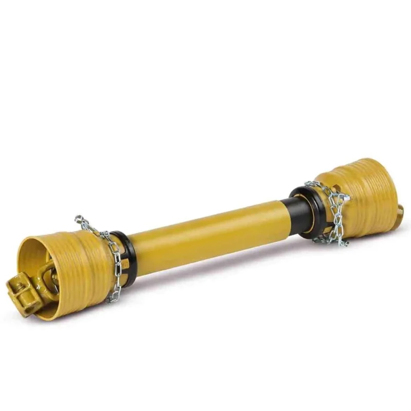
Overview: PTO Shaft for Potato Planter
Potato planting in Australia — from the rich volcanic soils of Gippsland and the South-East to the irrigated sandy loams of the Riverina and the Atherton Tablelands — demands precise seed-piece placement at consistent depth and spacing. PTO-driven potato planters use the shaft to drive their cup-chain or belt-type seed-metering mechanism, furrow openers, and fertiliser injectors simultaneously. GBC’s PTO Shaft for Potato Planter is built for this moderate-to-high torque, continuous-duty cycle, with low-vibration balanced tubes, a friction clutch to protect the planter’s metering and fertiliser-injection gearbox, and corrosion-resistant finishes for the wet, irrigated conditions of potato farming. Every shaft ships complete with AS/NZS-compliant guards, bearing supports and restraint chains.

Technical Specifications — PTO Shaft for Potato Planter
Key parameters for our potato planter PTO shaft. Custom specifications available on request.
| Parameter | Specification | Customisable Range |
|---|---|---|
| Shaft Series | Series 4 / Series 5 / Series 6 | Custom on request |
| Rated PTO Speed | 540 RPM | Standard |
| Continuous Torque | 400 – 850 Nm | Up to 1200 Nm |
| Peak Torque | 800 – 1700 Nm | 200% of continuous |
| Tractor-End Spline | 6-spline 1-3/8″ | 20-spline available |
| Implement-End Spline | 6-spline 1-3/8″ | Custom profiles |
| Closed Length (Lz) | 780 mm | 700 – 1100 mm range |
| Overall Length (Lo) | 1120 mm | 1000 – 1500 mm range |
| Telescopic Stroke | 340 mm | Up to 450 mm |
| Profile Tube Shape | Lemon (outer/inner) | Triangular available |
| Tube Wall Thickness | 3.0 mm | 3.5 mm reinforced |
| Tube Material | Cold-drawn steel, phosphate-coated | Zinc-nickel yokes |
| U-Joint Cross Size | 27 × 74.6 mm | 30.2 × 92 mm upgrade |
| U-Joint Bearing Type | Needle roller, multi-lip sealed | Pre-packed grease |
| U-Joint Max Angle | 25° | CV option |
| Overload Clutch | Multi-plate friction clutch | Adjustable |
| Clutch Torque | 450 Nm (adjustable) | 300 – 900 Nm range |
| Surface Treatment | Zinc-nickel plate + phosphate | Wet-condition rated |
| Guard Material | HDPE UV-stabilised | Chain-restrained |
| Total Weight | 10.5 kg | Varies by spec |
⚙️ How It Works: PTO Shaft in Potato Planter Applications
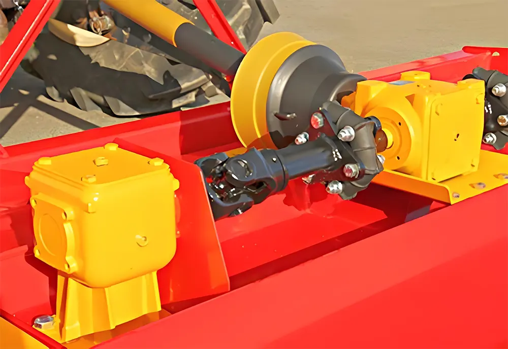
The PTO shaft connects the tractor’s 540 RPM PTO to the potato planter’s main drive gearbox. Inside the gearbox, a chain-and-sprocket system distributes power to each row unit’s cup-chain or belt seed-metering mechanism, the furrow-opening discs, the fertiliser metering system and the closing/hilling discs. The PTO shaft’s telescopic tubes and universal joints absorb distance and angle changes between the tractor and the trailing planter. A friction clutch at the implement end protects the planter’s gearbox from overload — a frequent occurrence when damp soil bridges around the furrow openers or a seed piece jams in the cup chain. Guards with chain restraints enclose all rotating parts per AS/NZS 1121.

PTO Shaft Anatomy: Understanding Every Component for Potato Planter Applications
Understanding the individual components of your potato planter PTO shaft helps you diagnose problems faster, communicate accurately with suppliers and make informed purchasing decisions. Here is a detailed breakdown of each major component and its function in the context of potato planter operations:
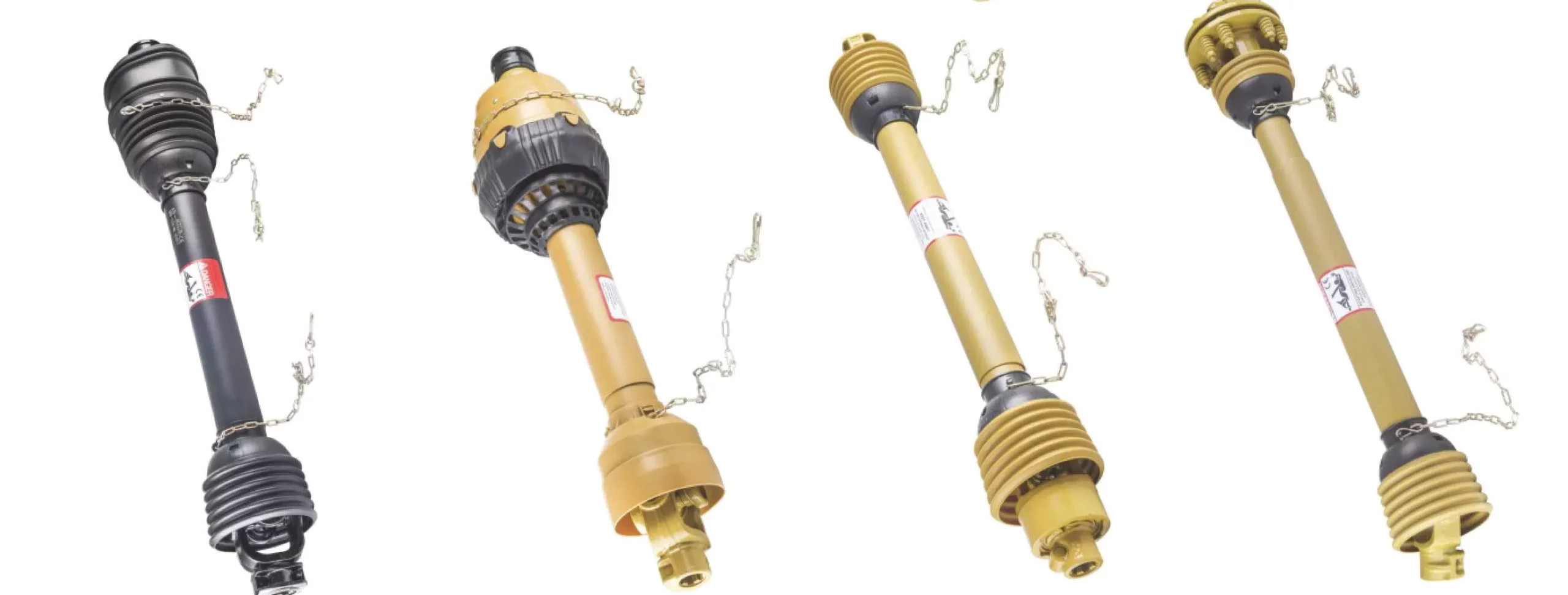
1. Tractor-End Yoke and Locking Collar: The tractor-end yoke is the component that slides onto the tractor’s PTO stub shaft. It is manufactured from case-hardened alloy steel (typically equivalent to SAE 4140) and features a quick-release locking collar with a spring-loaded pin that engages the groove machined into the PTO stub. This collar must be fully engaged before operation — a partially engaged collar can allow the shaft to fly off the stub under load, with extreme force. GBC yokes are precision-bored to match standard 6-spline (1-3/8″ / 35 mm) and 20-spline (1-3/4″ / 45 mm) PTO stubs. The locking collar is manufactured from forged steel and heat-treated for long service life.
2. Universal Joints (Cardan Joints): Each PTO shaft has two universal joints — one at the tractor end and one at the implement end. Each U-joint consists of a cross-shaped trunnion (the ‘cross’) with four arms, each fitted with a needle-roller bearing cup sealed with multi-lip nitrile-rubber seals. The U-joints allow the shaft to operate at angles up to 25° (standard) or 80° (with CV joint option) to accommodate the angular misalignment between the tractor PTO and the potato planter’s gearbox input. The bearing cups are pressed into the yoke ears and retained by snap rings. GBC U-joint crosses are manufactured from case-hardened chromium-molybdenum steel, heat-treated to 58 HRC for maximum fatigue life. Each bearing cup contains 22–28 precision-ground needle rollers that distribute the load evenly around the trunnion journal.
3. Telescopic Profile Tubes (Inner and Outer): The telescopic section consists of two tubes that slide within each other via matching spline profiles. This allows the shaft length to change continuously during operation as the distance between the tractor and the potato planter varies due to terrain undulation, three-point-hitch movement or trailing-implement drawbar geometry. Common profile shapes are lemon (two parallel flats), triangular (three-sided) and star (six-pointed). The inner tube is typically smaller in cross-section and slides inside the outer tube. Spline surfaces are induction-hardened to 55 HRC and coated with manganese phosphate for wear resistance. GBC tubes are manufactured from cold-drawn seamless alloy steel (EN 10305-3) for consistent wall thickness and torsional strength.
4. Implement-End Yoke and Overload Clutch: The implement-end yoke connects to the potato planter’s gearbox input shaft. On GBC PTO shafts, this yoke typically incorporates the overload clutch assembly — either a shear-bolt type (where a sacrificial bolt snaps to interrupt torque) or a multi-plate friction type (where spring-loaded friction plates slip momentarily and re-engage automatically). The friction clutch is GBC’s recommended option for potato planter applications because it absorbs transient overloads without stopping work. The clutch torque setting is adjusted by changing the spring preload — GBC factory-calibrates this to match the typical gearbox rating of potato planter equipment.
5. Safety Guard Assembly: The guard consists of two free-spinning plastic (HDPE) tubes, one covering each half of the shaft, supported on maintenance-free sealed bearings at each end. The guard tubes are UV-stabilised for Australian conditions and resist cracking for 5+ years in full sun. At each end, the guard bearing support is attached to the tractor guard bracket and the potato planter guard bracket by restraint chains — these prevent the guard from rotating with the shaft if a bearing fails, which would otherwise create a dangerous entanglement hazard. The guard assembly complies with AS/NZS 1121 and CE safety standards.
6. Grease Zerks (Nipples): Each U-joint and, on some models, the telescopic spline section are fitted with grease zerks (also called Zerk fittings or grease nipples) to allow periodic lubrication. GBC uses flush-mounted zerks with check valves that prevent dirt ingress between greasing events. The recommended lubricant is EP2 lithium-complex grease conforming to NLGI Grade 2.
7. Restraint Hardware: Each shaft is supplied with chains, brackets, bolts and safety decals as required by AS/NZS 1121 and CE standards. These are not optional accessories — they are integral safety components that must be correctly installed and maintained throughout the shaft’s service life.
Core Advantages of Our Potato Planter PTO Shaft
Consistent Cup-Chain Speed
Dynamic balancing ensures the PTO shaft delivers jitter-free rotation to the cup chain, maintaining even seed-piece spacing for uniform plant stands and optimal tuber sizing.
Wet-Condition Corrosion Resistance
Potato planting requires irrigated, moist soils. Our zinc-nickel plated yokes and phosphate-coated tubes resist the moisture and fertiliser that corrode uncoated shafts.
Friction Clutch Protects Gearbox
Cup-chain jams and fertiliser-injector blockages create sudden torque spikes. Our calibrated friction clutch absorbs these without damage.
Compact-to-Extended Length Range
Available from 700 mm to 1,500 mm overall length, covering everything from 2-row compact planters to 6-row trailing units.
Low-Maintenance Sealed Joints
Multi-lip sealed U-joints with pre-packed long-life grease reduce the maintenance burden during the intensive potato-planting window.
Affordable OEM Alternative
Equivalent quality to OEM shafts at 40–55% less cost — significant savings when equipping multi-row planting fleets.
Brand Compatibility & Replacement Guide
The GBC PTO Shaft for Potato Planter is a direct drop-in replacement for OEM shafts on:
Compatible Brands: Grimme, Structural (Miedema), Hassia, Dewulf, Standen, AVR, Lockwood, Spudnik, Gruse, Checchi & Magli, Imac
⚠️ Brand names are property of their respective owners, listed for compatibility reference only.
Replacement Parts
- U-joint cross-and-bearing kits
- Friction clutch plates and springs
- Telescopic profile tube pairs
- Safety guard tubes and bearings
- Locking collars, shear bolts and hardware
Quick Selection Guide — PTO Shaft for Potato Planter
| Parameter | Options | How to Determine |
|---|---|---|
| Planter Row Count | 2 / 4 / 6 rows | More rows = higher torque demand |
| Tractor PTO Speed | 540 RPM | Standard for potato planters |
| PTO Spline | 6-spline 1-3/8″, 20-spline 1-3/4″ | Match both ends |
| Shaft Series | Series 4 – Series 6 | Based on row count and HP |
| Closed Length (Lz) | 700 – 1100 mm | Measure at closest position |
| Overall Length (Lo) | 1000 – 1500 mm | Measure at max extension |
| Overload Protection | Friction clutch | Essential for cup-chain protection |
| Profile Tube | Lemon / Triangular | Match planter gearbox |
Need Help? Contact Our Engineers
Installation Guide — PTO Shaft for Potato Planter
Park and Secure
Level ground; handbrake on, engine off, key removed.
Verify Specs
Match spline, speed and diameter.
Set Length
Extend; ≥1/3 overlap at max extension.
Pre-Grease
EP2 grease all points — irrigated soil creates moisture everywhere.
Connect Tractor End
Lock yoke onto PTO stub.
Connect Planter End
Attach clutch-end yoke; verify lock.
Phase Shaft
Align yoke ears.
Install Guards
Fit guard assembly; verify clearance.
Test Run
Idle PTO, then operating RPM. Run planter through test row; check seed-piece spacing.
PTO Shaft Safety Best Practices — Potato Planter Operations
Power take-off shafts are one of the most dangerous components on any agricultural machine. In Australia, PTO-related incidents account for a significant proportion of serious farm injuries each year. Following these safety best practices when operating your potato planter PTO shaft is essential to protect yourself, your workers and your family.
Never Approach a Running PTO: Do not step over, reach across or stand near a rotating PTO shaft, even if it is fully guarded. If any adjustment, inspection or repair is needed, shut the tractor engine off completely, remove the ignition key and wait for all rotating components to come to a complete stop before approaching.
Wear Appropriate Clothing: Loose clothing, dangling drawstrings, long hair, scarves, ties and jewellery can be caught by a rotating PTO shaft in a fraction of a second. Always wear close-fitting clothing, secure long hair and remove jewellery before working near PTO-driven equipment.
Maintain Guards at All Times: Never operate the potato planter PTO shaft with guards removed, damaged or improperly secured. Check that both guard tubes rotate freely, that all restraint chains are intact and correctly tensioned, and that guard bearing supports are firmly attached to both the tractor and implement guard brackets. Under Australian law (Safe Work Australia codes and state WHS regulations), operating a PTO without compliant guards is a criminal offence that can result in fines, prosecution and increased insurance premiums.
Always Shut Down Before Unclogging: If the potato planter mechanism jams — regardless of how minor the jam appears — disengage the PTO, shut the engine off, remove the key and wait for all rotation to cease before attempting to clear the blockage. Many of the most severe PTO injuries occur when operators attempt to clear jams with the PTO engaged or the engine running.
Use the Correct Shaft: Never use a PTO shaft that is too long, too short, the wrong speed rating or the wrong spline configuration for your potato planter. An incorrectly sized shaft can separate under load, bottom out and buckle, or transmit the wrong speed to the implement — all of which create serious safety hazards.
Inspect Before Every Use: Before engaging the PTO at the start of each operating session, perform a visual walk-around inspection: check that both yoke locking mechanisms are fully engaged, guards are intact and free-spinning, chains are secure, and no tools or debris are resting on the shaft or implement. This 60-second habit can prevent catastrophic failures.
Train All Operators: Ensure that every person who operates the tractor and potato planter combination has been trained in PTO safety, understands the emergency shutdown procedure and knows the location of the PTO engagement control. Under Australian WHS law, the person conducting the business or undertaking (PCBU) has a duty to provide information, training and instruction to workers.
Keep Children and Bystanders Away: Establish an exclusion zone around all PTO-driven equipment during operation. Children and untrained bystanders must never be permitted near operating PTO machinery.
Understanding Overload Clutch Types for Potato Planter PTO Shafts
Choosing the correct overload clutch type for your potato planter PTO shaft is an important decision that affects both equipment protection and operational efficiency. Here is a detailed comparison of the three main clutch types offered by GBC:
Shear-Bolt Clutch (Type SB): The simplest and most affordable overload protection device. A grade-8.8 or grade-10.9 bolt connects the drive yoke to the clutch body. When torque exceeds the bolt’s shear strength, the bolt snaps, instantly disconnecting the shaft from the potato planter’s gearbox. The operator must stop, replace the bolt and resume work. Shear-bolt clutches are best suited for applications where overload events are infrequent and the cost of brief downtime is acceptable. They are commonly used on lighter-duty potato planter configurations where jams are rare. Advantages: lowest cost, simplest mechanism, easy to understand. Disadvantages: requires a full stop to replace the bolt; if overloads are frequent, the repeated stops reduce productivity and the bolt inventory becomes a nuisance.
Friction Clutch (Type FF): GBC’s recommended overload device for most potato planter applications. Multiple spring-loaded friction plates transmit torque through surface friction. When torque exceeds the spring preload, the plates slip — absorbing the overload energy as heat — and re-engage automatically as soon as the torque returns to normal. The operator may not even notice a brief slip event. The torque threshold is adjustable by changing the spring preload (compressing or extending the clutch springs). Advantages: automatic re-engagement without stopping; adjustable torque setting; absorbs transient spikes that would break a shear bolt; ideal for applications with frequent light overloads. Disadvantages: higher initial cost than shear-bolt; friction plates wear over time and require periodic inspection/replacement; can overheat if slipping is continuous (indicating the shaft series is under-rated).
Ratchet Clutch (Type RA): A free-wheel mechanism where spring-loaded pawls engage with a toothed ratchet ring to transmit torque in one direction. When overload occurs, the pawls momentarily disengage (producing an audible clicking sound) and re-engage on the next tooth. Ratchet clutches are designed for applications with frequent, repetitive impact loads — such as flail shredders and some types of aggressive tillage equipment. For standard potato planter applications, friction clutches are generally preferred unless the duty cycle involves high-frequency impact events. Advantages: handles repetitive impacts well; automatic re-engagement; audible feedback during overload. Disadvantages: produces a clicking noise during slip (can be confused with a fault); not as smooth as friction-clutch slip; higher cost.
How to Choose: For most potato planter operations, a friction clutch (Type FF) provides the best balance of protection, convenience and reliability. If your potato planter rarely jams and budget is a priority, a shear-bolt clutch (Type SB) is adequate. If your operation involves frequent impact events, consider a ratchet clutch (Type RA) or contact GBC’s engineers for a specific recommendation based on your equipment and operating conditions.
️ Troubleshooting — Potato Planter PTO Shaft
⚠️ Uneven seed-piece spacing
Cause: PTO shaft vibration or phase error
Solution: Re-phase; check U-joints; verify balance
⚠️ Cup chain jams repeatedly
Cause: Debris in mechanism or clutch not absorbing spikes
Solution: Clear debris; check clutch calibration
⚠️ Shaft corrodes quickly
Cause: Unprotected shaft in irrigated conditions
Solution: Switch to GBC zinc-nickel coated shaft
⚠️ Guard cracked
Cause: UV or mechanical damage
Solution: Replace with GBC UV-stabilised guard
⚠️ Clutch slips during normal planting
Cause: Plates worn from wet-soil contamination
Solution: Replace clutch plates; seal better
⚠️ Telescopic tubes stiff
Cause: Soil moisture in splines
Solution: Clean, apply anti-seize, re-grease
Maintenance & Lubrication Schedule — Potato Planter PTO Shaft
Maintaining your potato planter PTO shaft according to the recommended schedule is essential for safe operation and maximum service life. Australian conditions — characterised by heat, dust, UV exposure and in some regions, high humidity — demand a disciplined maintenance approach.
Every 6–8 Operating Hours: Grease both universal joints via their grease zerks using EP2 lithium-complex grease. Pump grease until a slight purge appears at each seal lip, confirming the bearing cavity is fully charged and contaminants have been displaced. In particularly dusty or corrosive conditions, reduce this interval to every 4 hours.
Every 15–20 Operating Hours: Lubricate the telescopic spline tubes. Separate the shaft halves, wipe the spline surfaces clean, apply a generous coat of EP2 grease to the full splinelength, and reassemble. Contaminated or dry splines wear rapidly and can seize, preventing the shaft from adjusting to distance changes between the tractor and the potato planter.
Every 50 Operating Hours: Perform a thorough inspection. Check each U-joint for radial play by gripping both yokes and trying to rock them — any detectable play indicates bearing wear and signals that a cross-and-bearing kit replacement should be scheduled. Inspect the overload clutch for correct calibration, check all guard tubes for cracks or UV damage, verify that guard bearings rotate freely, and confirm that restraint chains are intact and properly tensioned.
End of Season / Extended Storage: Fully disassemble the shaft. Clean all components with a solvent-dampened cloth. Inspect splines, tubes, yokes and U-joint bearings for wear. Re-grease all service points and apply anti-seize compound to spline surfaces to prevent corrosion during storage. Store the shaft horizontally in a dry, covered location away from direct sunlight and moisture. Replace any guards showing UV cracking or mechanical damage before the next season.
After Exposure to Corrosive Materials: If the shaft has been exposed to fertiliser dust, manure, chemical sprays or salt-laden coastal air, pressure-wash the entire shaft assembly with clean fresh water as soon as possible after use, then re-grease all service points. Corrosive residues left on metal surfaces accelerate pitting and bearing failure even during short storage periods.
How to Measure & Select the Correct PTO Shaft for Your Potato Planter
Selecting the correct PTO shaft length for your potato planter is the most important decision in the purchasing process. An incorrectly sized shaft is both a safety hazard and a potential source of expensive equipment damage. Use this step-by-step guide to determine the correct specifications:
Step 1 — Measure the Closed Length (Lz): With the potato planter attached to the tractor, raise the three-point hitch to its highest transport position (for hitch-mounted implements) or position the trailing drawbar at its shortest geometry (for trailing implements during tight turns). Measure the straight-line distance from the face of the tractor PTO stub shaft to the face of the potato planter’s gearbox input shaft. The PTO shaft’s closed length (Lz) must be at least 50 mm shorter than this measurement to prevent the shaft from bottoming out.
Step 2 — Measure the Overall Length (Lo): Lower the implement to its maximum working depth or extend the trailing drawbar to its longest geometry (for trailing implements on undulating terrain). Measure the same PTO-to-gearbox distance. The shaft’s overall length (Lo) must exceed this measurement by at least 50 mm. Critically, the telescopic tube overlap at this extended position must remain at least one-third of the total tube length — insufficient overlap risks spline separation under load, which is an extremely dangerous failure mode.
Step 3 — Check the Operating Angle: Visually assess the angle between the PTO shaft and the tractor’s PTO stub at the normal working position. Standard universal joints tolerate up to 25° of angular misalignment. If the angle appears steeper — particularly common with compact tractors, high-frame implements or combination rigs — contact GBC about the wide-angle constant-velocity (CV) joint option, which allows angles up to 80°.
Step 4 — Confirm Spline Specifications: Count the number of splines on the tractor PTO stub shaft. Common configurations are 6-spline (1-3/8″ / 35 mm diameter) and 20-spline (1-3/4″ / 45 mm diameter). Repeat for the potato planter’s gearbox input shaft. Both ends of the PTO shaft must match these specifications precisely — cross-referencing with the tractor and implement owner’s manuals is strongly recommended.
Step 5 — Identify the Profile Tube Shape: Examine the potato planter’s gearbox input. The cross-sectional shape of the input tube will be lemon (two parallel flats), triangular (three-sided) or star (six-pointed). The PTO shaft’s implement-end profile tube must match this shape exactly for proper engagement and torque transfer.
Need Assistance? GBC’s engineering team provides free measurement verification. Send us photos of the tractor PTO stub, the potato planter gearbox input and the measurements from Steps 1–2. We will confirm the correct shaft specification and ship it directly to your property.
Performance Comparison: GBC vs. Generic PTO Shafts for Potato Planter
| Feature | GBC PTO Shaft | Generic / Budget Shaft | Benefit |
|---|---|---|---|
| U-Joint Seal Type | Multi-lip nitrile with grease check valve | Single-lip rubber | 3× longer bearing life in contaminated environments |
| Spline Surface Hardness | 55 HRC induction-hardened + phosphate coat | Untreated mild steel | Dramatically slower wear in dusty/abrasive conditions |
| Yoke Corrosion Protection | Zinc-nickel plating (1,000+ hr salt-spray) | Bare steel or thin zinc | Multi-season corrosion resistance |
| Guard UV Rating | UV-stabilised HDPE (5+ years in AU sun) | Standard HDPE (1–2 seasons) | No premature guard replacement |
| Overload Clutch | Factory-calibrated to implement rating | Generic / one-size-fits-all | Correct protection without nuisance trips |
| Tube Wall Thickness | 3.0–4.0 mm (reinforced options) | 2.0–2.5 mm standard | Greater torsional rigidity and fatigue life |
| Dynamic Balance | ISO 1940 G6.3 certified | Not tested / not specified | Smooth operation, reduced implement wear |
| Included Guard Kit | Complete: tubes, bearings, chains, decals | Guard tubes only | Immediately AS/NZS 1121 compliant |
️ Seasonal Best Practices for Potato Planter PTO Shafts in Australia
Australian agricultural operations span every climate zone, and potato planter PTO shafts face different challenges depending on location and season:
Tropical North (Queensland, Northern Territory): High temperatures accelerate grease breakdown. Use a high-temperature EP2 grease formulation with a drop point above 260°C. Humidity promotes corrosion — inspect shaft surfaces regularly for rust spots and address them immediately with zinc-rich touch-up paint. UV intensity is extreme; monitor guard tube condition closely and replace at the first sign of surface cracking or embrittlement.
Temperate South-East (Victoria, Tasmania, Southern NSW): Cool, damp conditions with frequent morning dew create a moisture-rich operating environment. Grease all service points before starting work each morning to displace overnight moisture from bearing surfaces. Mud accumulation around the telescopic section can force contaminants into the spline interface — clean daily. Store the shaft in a dry shed overnight rather than leaving it exposed on the implement.
Arid Interior (South Australia, Western NSW, Western Queensland): Fine airborne dust is the primary enemy. In these conditions, the U-joint greasing interval should be reduced to every 4 operating hours without exception. Neoprene spline dust boots may require more frequent inspection as the UV-and-heat combination accelerates rubber degradation.
Coastal Regions (All States): Salt-laden air accelerates corrosion, particularly on steel surfaces that have been scratched or where coating has been damaged. GBC’s zinc-nickel plating provides excellent salt-spray resistance (1,000+ hours in ASTM B117 testing), but any coating damage should be repaired promptly with zinc-rich primer.
General Best Practices: Always allow the PTO shaft to reach operating temperature gradually by engaging the PTO at idle and increasing speed over 30–60 seconds. Cold grease has higher viscosity and provides less effective protection during the first few revolutions. After operation, if possible, run the PTO at idle for 30 seconds before disengaging to allow the grease to redistribute evenly around bearing surfaces.
Field Application Guide — Operating Your Potato Planter PTO Shaft in Australian Conditions
Here is a field application guide for operating your potato planter PTO shaft in Australian conditions:
Pre-Operation Check: Before each operating session, perform a quick walk-around inspection. Verify that both yoke locking mechanisms are fully engaged by tugging on each end of the shaft. Confirm that all guard tubes spin freely by hand. Check that restraint chains are intact and correctly tensioned. Look for any visible damage, corrosion or contamination on the shaft assembly. This 60-second check catches issues before they escalate into failures.
Warm-Up Procedure: When starting work for the day, engage the PTO at idle speed and allow the shaft to run for 30–60 seconds before increasing to operating RPM. This warm-up period allows grease to distribute through bearing surfaces and reduces the thermal shock on U-joint components. In cold conditions (below 10°C, common in southern Australian mornings during autumn sowing), extend the warm-up to 90 seconds.
Monitoring During Operation: Periodically check the PTO shaft during rest stops or refuelling breaks. Look for unusual vibration, heat (particularly at the U-joints — they should be warm but not too hot to touch) or any change in the sound of the shaft or the potato planter. A change in noise pattern — such as a new knocking, clicking or grinding sound — is an early warning of developing component wear that should be investigated before it becomes a failure.
Managing Terrain Variation: Australian farmland ranges from billiard-table flat to steeply undulating. On hilly or undulating ground, the PTO shaft’s universal joints work harder to accommodate the constantly changing angle between the tractor and the potato planter. If your operation involves significant terrain variation, monitor U-joint temperature more frequently and consider GBC’s wide-angle CV joint option if the angle regularly exceeds 15°.
Dust and Contamination Management: Dust is the number-one enemy of PTO shaft longevity in Australian conditions. Fine airborne soil particles — particularly the reactive clay minerals found in Australian black-soil and red-soil zones — act as an aggressive abrasive when they penetrate spline interfaces and bearing seals. Maintain the recommended greasing intervals strictly, and if operating in visibly dusty conditions, halve the interval. After each operating session, consider wiping down the exposed shaft surfaces with a damp cloth to remove accumulated dust before it migrates into sealed areas.
Corrosive Material Exposure: If your potato planter operation involves exposure to fertiliser dust, chemical sprays, manure, irrigation water or salt-laden coastal air, rinse the entire shaft assembly with clean fresh water as soon as possible after use. Corrosive residues left on metal surfaces — even for a few hours overnight — can initiate pitting corrosion that shortens component life. After rinsing, re-grease all service points to displace moisture and restore the protective grease film.
Storage Between Sessions: If the potato planter is not used daily, store the shaft in a dry, covered location between sessions. If the shaft must remain on the implement between uses, ensure that the guards are intact to protect the shaft from direct sun, rain and dust accumulation.
Record Keeping: Maintain a simple log of shaft operating hours, grease dates, inspections and parts replaced. This record supports warranty claims, helps predict maintenance needs and demonstrates WHS compliance. A notebook kept in the tractor cab or a note in your farm management app is sufficient.
Australian Case Studies — Potato Planter PTO Shaft
Ballarat, VIC — Potato grower planting 600 ha with 4-row Grimme planters
“The friction clutch is perfectly calibrated — never slips during normal operation but protects the gearbox when cups jam. Build quality is OEM-equivalent at half the price.”
Crookwell, NSW — Seed-potato producer using a 2-row Structural planter
“Compact shaft that fits our narrow-track tractor. The sealed U-joints handle the constant moisture without issue.”
Atherton Tablelands, QLD — Tropical potato grower with a 4-row planter
“Heat, humidity and red soil — tough conditions. The GBC shaft’s corrosion protection is holding up far better than what we had before.”
Penola, SA — Commercial potato grower planting 400 ha with Grimme GL 660
“We run three planting rigs and fitted GBC shafts to all. Consistent quality across all units and the price made fleet replacement affordable.”
Pemberton, WA — Potato and vegetable grower using a Hassia planter
“The extended overall length covers our longer drawbar setup. Good shaft at a fair price.”
Forthside, TAS — Major seed-potato producer using Dewulf planters
“Tasmania’s premier potato region demands the best equipment. The GBC shaft matches the Dewulf specification perfectly and the local after-sales support is responsive.”
❓ FAQ — PTO Shaft for Potato Planter
❔ What shaft series for a 4-row potato planter?
Series 5 typically. Series 6 for heavy soils or if the planter includes a powered fertiliser injector.
❔ How does moisture affect PTO shaft life?
Moisture accelerates corrosion and washes lubricant from unprotected surfaces. GBC’s zinc-nickel coating and sealed bearings are designed for irrigated conditions.
❔ Grease frequency?
U-joints every 8 hours; splines every 15 hours. Wet conditions demand vigilance.
❔ Compatible with Grimme planters?
Yes — drop-in fit for all Grimme PTO-driven models.
❔ Warranty?
12 months, fleet extensions available.
PTO Speed Matching Guide — Getting the RPM Right for Your Potato Planter
One of the most critical specifications when selecting a PTO shaft for your potato planter is the PTO speed — measured in revolutions per minute (RPM). Using the wrong PTO speed can damage the potato planter’s gearbox, void its warranty and create a safety hazard. Here is a comprehensive guide to understanding and matching PTO speeds in Australian agricultural applications:
Standard PTO Speeds: Australian tractors typically offer one or two PTO speed options: 540 RPM (the most common standard) and 1000 RPM (used on higher-powered tractors and implements that require faster rotational input). Some tractors also offer 540E (economy PTO), which delivers 540 RPM at a reduced engine speed to save fuel during light-duty operations. A smaller number of older or specialised tractors may offer 750 RPM or other non-standard speeds.
How to Identify Your Tractor’s PTO Speed: Check the operator’s manual for your tractor model. The PTO stub shaft itself also provides a visual clue: 540 RPM stubs typically have 6 splines at 1-3/8 inch (35 mm) diameter, while 1000 RPM stubs typically have 21 splines at 1-3/8 inch or 20 splines at 1-3/4 inch (45 mm) diameter. Some tractors have a selectable dual-speed PTO with a changeover mechanism on the stub — consult your tractor manual for the correct operating procedure.
How to Identify Your Potato planter’s Required Input Speed: The potato planter manufacturer’s manual will specify the required PTO input speed. This is non-negotiable — the potato planter’s gearbox, metering mechanism and other driven components are designed to operate at a specific speed. Running a 540 RPM implement at 1000 RPM effectively doubles the component speeds, causing extreme wear, overheating and potential catastrophic failure. Conversely, running a 1000 RPM implement at 540 RPM delivers insufficient power and may stall the mechanism under load.
Matching the PTO Shaft: The GBC PTO shaft you select must be rated for the correct speed. A 540 RPM shaft and a 1000 RPM shaft may look identical externally, but they differ in bearing specification, balance grade and overload clutch calibration. When ordering from GBC, always specify the PTO speed to ensure you receive a shaft that is correctly configured for your tractor-potato planter combination.
540E (Economy PTO) Considerations: The 540E setting delivers 540 RPM at a reduced engine speed — typically around 1,500–1,600 RPM instead of the standard 1,900–2,100 RPM. This saves fuel and reduces noise, making it attractive for light-duty operations such as some seeding and spreading applications. GBC PTO shafts rated for 540 RPM are fully compatible with 540E operation. However, confirm that the potato planter’s driven components (particularly hydraulic pumps and fans) can operate effectively at the slightly reduced engine power available in economy mode.
Common Speed-Mismatch Scenarios to Avoid: Never connect a 6-spline 540 RPM PTO stub to a 21-spline 1000 RPM implement input using an adapter sleeve — this mismatches the speed and can destroy the implement gearbox within minutes. If your tractor has a dual-speed PTO, always verify that the correct speed is selected before engaging. If you are unsure about any aspect of speed matching, contact GBC’s engineering team before operating the equipment.
Australian Regulations & Local SEO
Potato-planting operations must comply with AS/NZS 1121 PTO guard standards. State regulators enforce compliance, with WorkSafe Victoria particularly active in Gippsland and western VIC potato regions. GBC shafts ship fully compliant. SEO: ‘potato planter PTO shaft Australia’, ‘tuber planter drive shaft VIC’, ‘potato seeder PTO shaft NSW’, ‘potato planting PTO shaft TAS’.
Related Products
Complement your potato planter PTO shaft with these GBC products:

agricultural gearboxes
PTO shafts
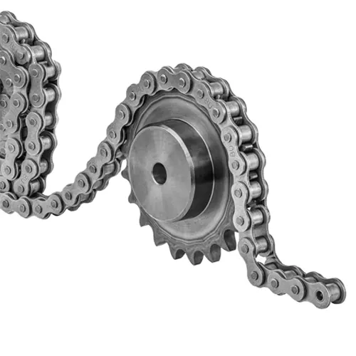
sprockets and chains

pulleys
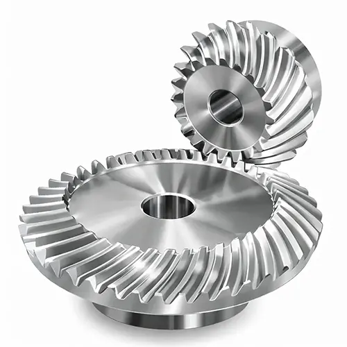
gears
How to Order Your Potato Planter PTO Shaft — Australian Shipping & Delivery
Ordering the correct PTO shaft for your potato planter from GBC is straightforward. Follow this process to ensure you receive the right shaft, delivered to your property as quickly as possible:
Step 1 — Gather Your Specifications: Before contacting GBC, collect the following information: your tractor make, model and PTO speed (540 or 1000 RPM); the potato planter make, model and gearbox input specification; the closed-length and overall-length measurements (see our measurement guide above); and the profile tube shape of the potato planter’s gearbox input (lemon, triangular or star). Having this information ready speeds up the selection process and ensures first-time accuracy.
Step 2 — Contact GBC: Reach out to our team via email at sales@australia-drive.com, through the contact form on our website at australia-drive.com/contact-us, or by phone during Australian business hours. Provide the specifications from Step 1 and our engineers will confirm the correct shaft model, series and options for your setup. There is no charge for this selection assistance.
Step 3 — Receive Your Quote: GBC provides itemised quotations that clearly list the shaft model, series, length, clutch type, guard kit and any optional extras (such as CV joint upgrades or custom lengths). Pricing includes GST for Australian customers. Dealer, fleet and volume pricing is available upon request.
Step 4 — Place Your Order: Orders can be placed by email, phone or through our website. Payment options include bank transfer, credit card and approved trade accounts for established dealers and repeat customers.
Step 5 — Shipping and Delivery: GBC maintains stock of popular shaft configurations at our Australian warehouse. In-stock items are dispatched within 24 hours of order confirmation. Standard shipping to metro areas (Sydney, Melbourne, Brisbane, Adelaide, Perth) typically takes 2–4 business days via major freight carriers. Regional and remote delivery timescales depend on location — most regional centres receive goods within 4–7 business days. Express freight options are available for urgent requirements during critical planting or harvest windows. Custom-length and non-standard shafts are manufactured to order with a typical lead time of 5–10 business days before dispatch.
Step 6 — Receiving and Inspection: Upon receipt, inspect the packaging for transit damage and verify that the shaft model, length and specifications match your order. GBC packs all PTO shafts in heavy-duty cardboard cartons with foam inserts to minimise transit damage. If any discrepancy or damage is noted, contact GBC immediately with photos and your order number for prompt resolution.
Returns and Exchanges: GBC offers a hassle-free exchange policy for incorrectly sized shafts, provided the shaft is unused and in its original packaging. Contact our team within 14 days of receipt to arrange an exchange. Freight costs for exchanges due to ordering errors are the customer’s responsibility; exchanges due to GBC errors are freight-free.
Warranty Registration: All GBC PTO shafts are covered by a 12-month manufacturer’s warranty from the date of purchase. Retain your invoice as proof of purchase. Warranty claims are handled by GBC’s Australian support team — no international correspondence required.
Total Cost of Ownership — Why GBC PTO Shafts Are the Smart Investment for Potato Planter Operations
When evaluating PTO shaft options for your potato planter, it is tempting to select the lowest-priced unit available. However, the true cost of a PTO shaft extends far beyond the purchase price. Consider the following total-cost-of-ownership factors:
Purchase Price: GBC PTO shafts are typically priced 40–55% below OEM replacement shafts from major implement manufacturers, while matching OEM material and tolerance standards. Compared to the cheapest no-name imports, GBC shafts may carry a modest premium — but the following cost factors demonstrate why that premium is recovered many times over.
Bearing and U-Joint Replacement: A cheap PTO shaft with single-lip U-joint seals operating in the dusty, abrasive conditions typical of Australian potato planter operations typically requires U-joint replacement every 200–400 operating hours. GBC’s multi-lip sealed joints routinely exceed 1,500 operating hours before replacement. At approximately AUD 80–120 per cross-and-bearing kit plus labour, this difference alone can save AUD 400–800 over the shaft’s lifetime.
Downtime Cost: A PTO shaft failure during a critical operating window — such as the narrow sowing period or the peak of harvest season — can cost far more in lost productivity than the shaft itself. In broadacre Australian agriculture, a single day of lost sowing time can represent AUD 5,000–20,000 in delayed planting and reduced yield potential. GBC shafts are engineered to minimise the probability of in-field failure through superior materials, precision manufacturing and correctly calibrated overload protection.
Implement Gearbox Damage: A PTO shaft without properly calibrated overload protection can transmit destructive torque spikes to the potato planter’s gearbox, hydraulic pump or metering mechanism. A replacement gearbox for a modern agricultural implement can cost AUD 3,000–15,000 — many times the price of a quality PTO shaft with factory-calibrated overload protection.
Guard Replacement: Budget shafts often ship with non-UV-stabilised guards that crack and disintegrate within 1–2 Australian seasons. Replacement guard kits cost AUD 80–150 each. GBC’s UV-stabilised HDPE guards are rated for 5+ years, eliminating this recurring cost.
Safety and Compliance: Operating with a damaged, unguarded or non-compliant PTO shaft exposes the operator to serious injury risk and the farm business to regulatory penalties, increased insurance premiums and potential litigation. GBC shafts ship fully compliant with AS/NZS 1121 and CE standards, with a complete guard kit included — reducing the risk of non-compliance and its associated costs.
Summary: When purchase price, maintenance costs, downtime risk, implement-protection value and safety compliance are all considered, a GBC PTO shaft delivers a significantly lower total cost of ownership than both cheap imports (which fail frequently) and OEM units (which are priced at a substantial premium for equivalent performance).
Why Choose GBC
We are GBC — General Bearing Company Pty Ltd., the official Australian agency of Ever-power Group. With 20+ years of manufacturing and exports to 50+ countries, we deliver world-class power-transmission products at competitive prices.
- Advanced Production: CNC machining, robotic welding, ISO 9001 quality.
- OEM & Custom: Prototype to volume — custom PTO shafts to your exact spec.
- Australian Stock: Popular configurations held locally for fast dispatch.
- 12-Month Warranty: Extended warranty and fleet programmes available.
- Engineering Support: Free selection assistance andtorque calculations.
Partner with GBC
Whether you need a single replacement PTO shaft for your potato planter or a bulk supply agreement, we offer competitive pricing, custom manufacturing, technical support and fast logistics.
Request a Quote — Contact GBC Now
Visit GBC Australia | Contact Us | Email: sales@australia-drive.com