
Bevel Gear
Bevel Gears for Sale

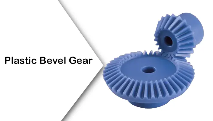
What are Bevel Gears?
Bevel gear is a mechanical transmission device for transmitting vertical (or non-parallel) motion and power between axes. The gear shape is conical, and the tooth surface is usually distributed on the outer surface of the cone, which can achieve smooth motion transmission between the staggered axes. Bevel gears are often used in scenarios where the Angle between the shafts is 90 degrees, but have the flexibility to adapt to other angles. According to the tooth type, bevel gear is divided into straight bevel gear (suitable for low speed or light load scenes), and spiral bevel gear (contact efficiency is higher, carrying capacity is stronger). Because of its ability to efficiently transfer power and adjust the direction, bevel gears are very important in practical applications, and are commonly found in equipment such as automotive differentials, industrial machinery, and railway systems that need to steer or change the direction of power transmission.


Bevel Gear Machining


Bevel gear is mainly used for the transmission of the intersection of two axes, and the Angle between the two axes is usually 90°, and can also be less than 90°. Bevel gear is generally processed on special machine tools such as cone gear planer, in the absence of special machine tools for bevel gear, it can be processed on the milling machine with bevel gear milling cutter, which uses forming tools and dividing devices to process on the milling machine. Due to the existence of indexing errors and tool installation errors, generally only 9-10 precision gears can be machined.
Bevel Gear in the Automotive Industry
Bevel gears in the differential
The automotive differential is one of the most typical application scenarios of bevel gears. When the vehicle turns, the inner and outer wheels need to rotate at different speeds. The differential achieves this function through a bevel gear set (usually a spiral bevel gear or a quasi-hyperbolic gear).
Technical details: The differential contains planetary Bevel gears (Pinion Bevel Gear) and Side bevel gears inside, and torque is distributed through the rotation and revolution of the planetary gears.
Advantages: The helical tooth design of the helical bevel gear can reduce meshing impact and lower noise. The axis offset characteristic of the Hypoid Gear makes the drive axle volume more compact and is suitable for rear-wheel drive or four-wheel drive models.
Bevel gears in the steering system
In the steering mechanisms of some heavy vehicles (such as trucks and construction machinery), bevel gears are used to convert the rotational motion of the steering wheel into the swing of the steering knuckle.
Technical details: Usually, straight bevel gears or spiral bevel gears are adopted in combination with a hydraulic power assistance system to achieve precise steering.
Advantages: The intersecting shaft transmission characteristics of bevel gears make the layout of the steering mechanism more flexible and adaptable to complex chassis structures.


Bevel Gear Production Process
- 1. First of all, using the principle of rolling and cutting, so that the processed gear and the imaginary spade gear each other repeatedly for the relative rolling and cutting work, the tool is the use of two straight-line cutting edge planer knife, mounted on the knife frame, and with the knife frame for reciprocating straight-line movement.


- 2. The tool holder is mounted on the rocking table, which forms the imaginary spade gear. The imaginary spade gear swings around its own axis line from up to down and from down to up, the processed gear is mounted on the main shaft of the gear box, move the gear box to make the processed gear’s bevel top coincide with the bevel top of the imaginary spade gear, and make the tooth root angle parallel to the surface passed by the tip of the knife.
- 3. When cutting the teeth, the rocking table and the processed gears each make coordinated motion around the axis center line to adapt to each other.
- 4. The axis line and the rotary axis line of the rocking table intersect at one point, which is the center of the machine tool. This mutual movement, so that the planer knife can plan the correct involute tooth shape.


Straight Bevel Gear VS Spiral Bevel Gear
Straight bevel gear is the simplest bevel gear, its teeth are straight, pointing to the apex of the cone. Straight bevel gears are easier to manufacture than spiral bevel gears and do not generate inward thrust (negative direction), thus simplifying the bearing structure. On the other hand, they have the disadvantage of not grinding teeth after heat treatment.
Straight bevel gears are usually used for relatively low speed applications (circular speed less than 2m/s). They are usually not used when large forces need to be transmitted. Generally used in machine tool equipment, printing press and differential.
Spiral bevel gear is a kind of gear with spiral curved teeth. Unlike straight bevel gears, these teeth touch each other gradually and smoothly from one end to the other. As with straight bevel gear, the tooth engagement is the rolling contact on the pitch cone.
The advantage of spiral bevel gears is that they can be ground after heat treatment, so high-precision gears can be produced. In addition, because the tooth contact ratio is higher than that of straight bevel gears, noise and vibration are reduced, making it more suitable for high-speed applications. For example, at high speeds (more than 10 m/s), noise and vibration are significantly reduced. They are also more robust and durable than straight bevel gears and can withstand greater loads. On the other hand, the manufacturing of spiral bevel gear is difficult
Spiral bevel gears need to be careful to change the direction of thrust according to the rotation and torsion Angle. These are some of its disadvantages.
When used, the right spiral gear is paired with the left spiral gear. In terms of applications, they are often used in automotive retarders and machine tools.


Get a Quote of GBC Bevel Gear
As the professional sales agent of Ever-power Group in the Australian region, GBC has always been committed to providing customers with high-quality products and excellent services. The bevel gear we supply has gained wide recognition in the Australian market with its excellent performance and reliable quality. At present, this series of products has successfully covered multiple states such as New South Wales, Victoria, and Queensland. The sales network has extended to major cities like Sydney, Melbourne, and Brisbane, and is also available for sale in cities like Adelaide and Perth. No matter which corner of Australia the customers are in, they can conveniently obtain our bevel gear to meet various industrial needs.