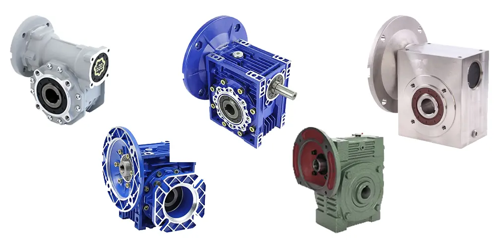
Worm gear reducers (Worm Gearbox) are widely used in industrial equipment due to their compact structure, large transmission ratio, and good self-locking performance. However, in the face of numerous models and parameters of worm gear reducers on the market, how to scientifically select a model has become a key skill that engineers and equipment purchasers must master.
Clarify application requirements
The first step in selection is to fully understand the actual working conditions and technical requirements of the equipment, mainly including:
- Load type: constant load, shock load or periodic load;
- Load size: Torque requirement (starting torque, operating torque);
- Working time: Is it intermittent operation or continuous operation?
- Operating speed: Input rotational speed and required output rotational speed;
- Environmental conditions: temperature, humidity, dust, corrosive media, etc.
- Installation space: axial space, flange size limitations, etc.
- Clarifying these requirements is helpful for screening out the most suitable model in the subsequent selection.
Determine the transmission ratio
The most notable feature of worm gear reducers is that they can achieve a large transmission ratio, typically ranging from 10:1 to 60:1. Some special designs can even reach 100:1 or higher.
The calculation formula for the transmission ratio is:
The transmission ratio i = input speed ÷ output speed
For example: If the motor speed is 1500 rpm and the required output speed is 50 rpm,
then: i = 1500 ÷ 50 = 30
A transmission ratio model close to 30:1 should be selected.
Calculate the required output torque
Output torque is one of the core parameters in the selection process. Based on the load and transmission ratio, the required output torque can be estimated:
T = (9550 × P) ÷ n
Among them:
T is the output torque (Nm)
P represents the motor power (kW)
n represents the rotational speed of the output shaft (rpm)
The calculated torque should be multiplied by the safety factor (generally 1.2 to 2.0) to ensure the stable operation of the reducer under actual working conditions.
Select the appropriate structural type
Worm gear reducers can be classified into various structural types based on their installation methods and output forms:
Installation methods: horizontal, vertical, flange installation;
Output methods: solid shaft, hollow shaft, double shaft output;
Input methods: direct motor connection, coupling input, pulley input, etc.
The appropriate structural form should be selected based on the installation space of the equipment and the transmission mode.
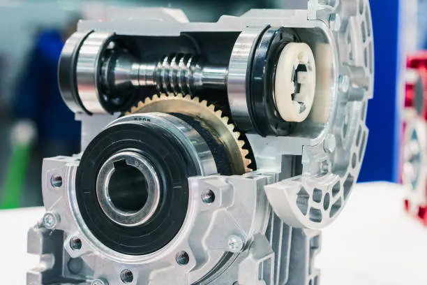
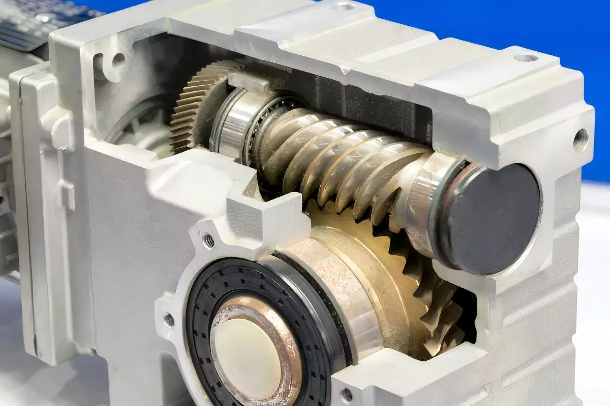
Considerations on Efficiency and Self-locking
The efficiency of worm gear reducers is usually between 30% and 90%, and is affected by the following factors:
The number of worm heads: The more heads there are, the higher the efficiency.
Pressure Angle and helix Angle: Reasonable design can reduce friction.
Lubrication conditions: The use of high-quality lubricating oil can effectively improve efficiency;
Load size: The greater the load, the more obvious the frictional loss.
If the equipment needs to prevent reverse rotation (such as elevators), a worm gear reducer with self-locking function should be selected.
Consider maintenance and lifespan
When choosing a worm gear reducer, attention should also be paid to its ease of maintenance and service life:
Whether it is easy to change the lubricating oil;
Whether it is equipped with an oil level observation window or an oil drain hole;
Whether there is a good sealing structure to prevent oil leakage;
Whether it supports the replacement of vulnerable parts such as bearings or oil seals.
Products with high reliability and convenient maintenance can effectively reduce the risk of equipment downtime and maintenance costs.
Analysis of Selection Examples
Example requirements:
Applied to a conveyor;
The motor power is 1.5kW and the input speed is 1400 rpm.
The required output speed is 70 rpm;
Continuous operation, running for 16 hours every day;
The ambient temperature is 40℃ and there is dust.
Selection steps:
Calculate the transmission ratio:
i = 1400 ÷ 70 ≈ 20
Calculate the output torque:
T = (9550 × 1.5) ÷ 70 ≈ 204.6 Nm
It is approximately 250 Nm after adding the safety factor
Select the structural type: horizontal installation, hollow shaft output;
The aluminum alloy shell with a fan is selected, which is suitable for high-temperature heat dissipation.
Considering efficiency and service life, choose a reducer model with double-ended worm gears and good lubrication.
Conclusion
The selection of worm gear reducers is a systematic project, involving multiple aspects such as transmission calculation, structural matching, and environmental adaptability. Only by comprehensively assessing the actual working conditions and combining reasonable parameter selection can the reliability and economy of equipment operation be guaranteed. It is recommended to communicate with the manufacturer or technical experts before selection to obtain the best configuration plan.