SWP-C Short Non-Flexible Universal Joint Couplings
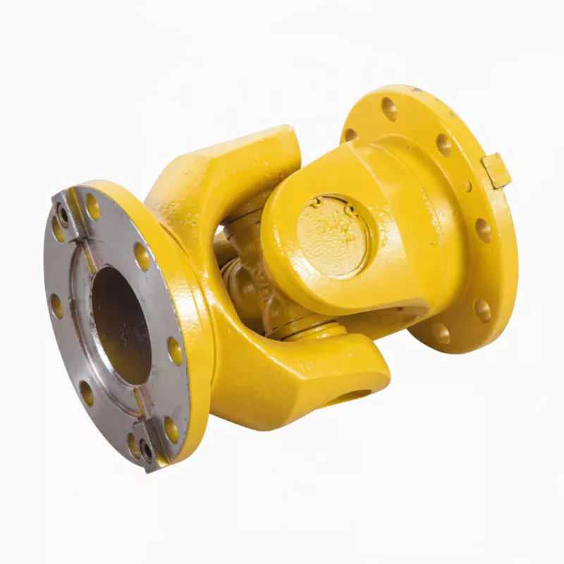
The SWP-C Short Non-Flexible Universal Joint Coupling is a compact, fixed-length split axletree spider-type cardan joint with no telescoping sleeve. Covering gyration diameters 160–640 mm and nominal torques 16–1 250 kN·m at ≤10° fold angle, SWP-C offers the shortest installed length and lowest rotational inertia in the SWP family — the right choice for power generation, cement, and fixed-shaft conveyor drives where axial displacement is absent and a rigid, low-maintenance drivetrain is preferred.
SWP-C Short Non-Flexible Universal Joint Couplings — Product Overview
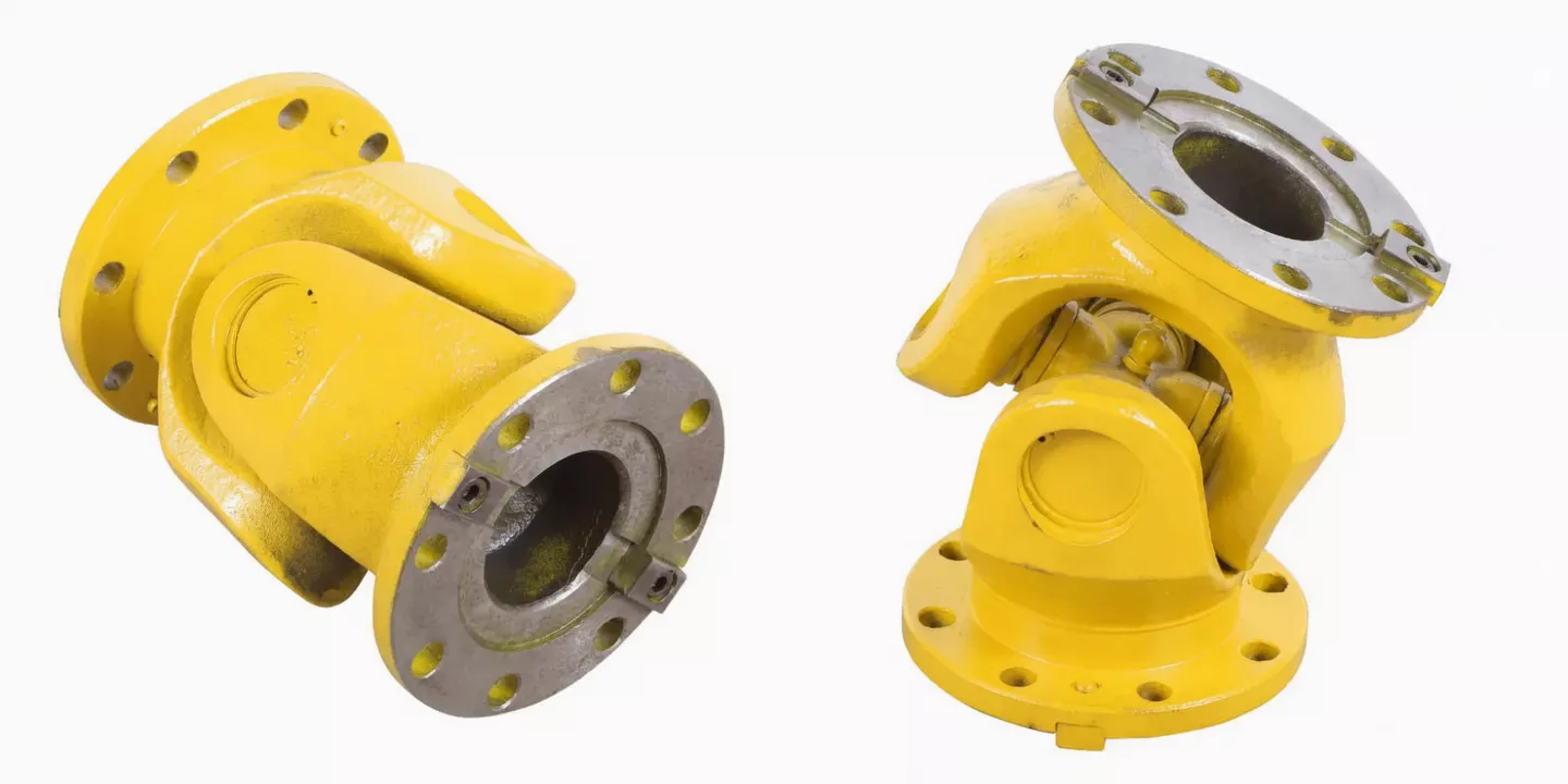
The SWP-C Short Non-Flexible Universal Joint Coupling is a split axletree, spider-type cardan joint for high-torque applications where shaft centre distances are fixed and no axial telescoping stroke is required. The defining difference from SWP-A and SWP-B is the absence of a sliding sleeve — the intermediate tube is a solid, fixed-length body, resulting in a stiffer, lower-inertia, and shorter installation envelope compared to flex-type equivalents at the same torque rating.
Despite lacking axial flexibility, the SWP-C fully retains the universal joint's angular misalignment compensation capability: the Hooke's joint mechanism transmits power across shaft angular offsets of ≤10° at full rated torque. The split axletree bearing housing remains — spider replacement is still achievable in situ without shaft disassembly, maintaining the maintenance advantage that defines the entire SWP series.
Gyration diameters span 160 mm to 640 mm, torques from 16 to 1 250 kN·m, and installed lengths from 340 mm (SWP160C) to just 1 540 mm (SWP640C) — significantly shorter than SWP-A or SWP-B equivalents. This compact footprint is a distinct advantage in power generation, cement, and conveyor applications where machinery layouts are optimised for minimum floor area.
Key structural distinction from SWP-A/B/D/E/F: No spline or sliding interface in the intermediate tube means the SWP-C has no relative motion between yokes along the shaft axis. This eliminates the sliding friction component, produces marginally lower rotational inertia, and reduces the number of lubrication points compared to flex-type couplings.
Typical Australian applications: Power station auxiliary drives (feed pump drives, induced draft fan drives), cement mill main and auxiliary drives, long conveyor intermediate drive stations where shaft positions are permanently anchored, mining hoists with fixed drum-to-gearbox geometry, and marine auxiliary shaft lines where axial shaft positions are locked by thrust bearings.
Technical Specifications
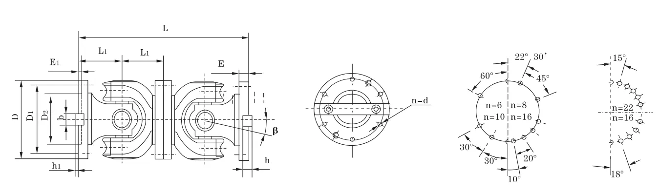
| Type | D (mm) | Tn (kN·m) | Tf (kN·m) | β | Lmin (mm) | D1 js11 | D2 H7 | E | E1 | b×h | h1 | L1 | n–d | I Lmin (kg·m²) | G Lmin (kg) |
|---|---|---|---|---|---|---|---|---|---|---|---|---|---|---|---|
| SWP160C | 160 | 16 | 8 | ≤10 | 340 | 140 | 95 | 15 | 4 | 20×12 | 6 | 85 | 6–13 | 0.11 | 31 |
| SWP180C | 180 | 20 | 10 | ≤10 | 380 | 155 | 105 | 15 | 4 | 24×14 | 7 | 95 | 6–15 | 0.17 | 42 |
| SWP200C | 200 | 31.5 | 16 | ≤10 | 440 | 175 | 125 | 17 | 5 | 28×16 | 8 | 110 | 8–15 | 0.29 | 59 |
| SWP225C | 225 | 40 | 20 | ≤10 | 520 | 196 | 135 | 20 | 5 | 32×18 | 9 | 130 | 8–17 | 0.51 | 80 |
| SWP250C | 250 | 63 | 31.5 | ≤10 | 540 | 218 | 150 | 25 | 5 | 40×25 | 12.5 | 135 | 8–19 | 0.93 | 119 |
| SWP285C | 285 | 90 | 45 | ≤10 | 600 | 245 | 170 | 27 | 7 | 40×30 | 15 | 150 | 8–21 | 1.88 | 179 |
| SWP315C | 315 | 140 | 63 | ≤10 | 680 | 280 | 185 | 32 | 7 | 40×30 | 15 | 170 | 10–23 | 2.88 | 232 |
| SWP350C | 350 | 180 | 90 | ≤10 | 740 | 310 | 210 | 35 | 8 | 50×32 | 16 | 185 | 10–23 | 4.59 | 300 |
| SWP390C | 390 | 250 | 112 | ≤10 | 820 | 345 | 235 | 40 | 8 | 70×36 | 18 | 205 | 10–25 | 8.64 | 432 |
| SWP430C | 430 | 355 | 160 | ≤10 | 940 | 385 | 255 | 42 | 10 | 80×40 | 20 | 235 | 16–28 | 17.41 | 688 |
| SWP480C | 480 | 450 | 224 | ≤10 | 1060 | 425 | 275 | 47 | 12 | 90×45 | 22.5 | 265 | 16–31 | 28.25 | 904 |
| SWP550C | 550 | 710 | 315 | ≤10 | 1160 | 492 | 320 | 50 | 12 | 100×45 | 22.5 | 290 | 16–31 | 49.49 | 1309 |
| SWP600C | 600 | 1000 | 500 | ≤10 | 1440 | 544 | 380 | 55 | 15 | 90×55 | 27.5 | 360 | 22–34 | 87.17 | 1377 |
| SWP640C | 640 | 1250 | 630 | ≤10 | 1540 | 575 | 385 | 60 | 15 | 100×60 | 30 | 385 | 18–38 | 152.76 | 2635 |
Note: SWP-C has no Ls (flex quantity) column — the shaft length is fixed. SWP430C replaces SWP435C in this type. Lmin is the sole installed length. Note that SWP-C produces lower rotational inertia than equivalent SWP-A/B sizes due to absence of sliding sleeve assembly.
Industry Applications
⚡ Power Station Auxiliary Drives (Feed Pumps, Fan Drives)
Working condition: Continuous 24/7 operation, critical service (pump failure triggers plant trip), high consequence of unplanned downtime.
Why SWP-C: In power station boiler feed pump and induced draft fan applications, shaft positions are precisely fixed by thrust bearing arrangements — no axial float is present or desired. The SWP-C's rigid body eliminates the telescoping interface (a potential wear point) and provides a stiffer, lower-maintenance drivetrain between motor, gearbox, and pump/fan.
Customer benefit: Fewer maintenance points, lower lubrication requirement, and reduced vibration transmission compared to sliding-sleeve types in fixed-shaft applications.
️ Cement Mill Main Drives
Working condition: Very high torque (>500 kN·m on large mills), low speed, abrasive dust environment, 300+ day annual operation.
Why SWP-C: Cement mill girth gear and pinion geometry is fixed during commissioning and does not change in service. The short non-flex type provides the required angular compensation without the added inertia or complexity of a sliding sleeve — important when the drive train inertia is already dominated by the mill body itself.
Customer benefit: Simplified maintenance schedule; no spline grease change required for the intermediate tube; longer overall MTBF in dust-contaminated environment.
Conveyor Intermediate Drive Stations
Working condition: Permanent installation, fixed-structure mounting points, moderate-to-high torque, minimal annual maintenance access.
Why SWP-C: Long conveyor intermediate drive stations (common in Australian iron ore and coal handling) anchor both motor and conveyor drive pulley in fixed structural frames. The SWP-C provides angular accommodation for minor frame settlement without the unused telescoping feature that would only add weight and inertia.
Customer benefit: Lighter drivetrain reduces structural load on conveyor gantry; simpler lubrication regime.
⚓ Marine Auxiliary Shaft Lines
Working condition: Vessel hull flex introduces angular misalignment between engine room auxiliaries; thrust bearings lock shaft axial positions.
Why SWP-C: Marine auxiliary shaft lines (generator drives, sea water pump drives) use thrust bearings to absorb propeller or pump axial loads — axial shaft float is not present. SWP-C provides the angular compensation for hull flex without introducing unwanted axial compliance that could load thrust bearings.
Customer benefit: Thrust bearing protected from unexpected axial coupling loads; drivetrain behaves predictably under hull deflection.
How to Choose the Right Coupling — SWP-C vs Flex Types
The SWP-C is frequently confused with SWP-B in specifications. The critical question is simple: does any axial shaft movement occur in your application? If yes — even 1–2 mm thermal growth — SWP-B or SWP-A is required. If shaft positions are rigidly fixed, SWP-C is the correct and more economical choice.
| Decision Factor | Choose SWP-C | Choose SWP-B or SWP-A Instead |
|---|---|---|
| Axial shaft movement in service | None — fixed positions | Any thermal growth, mechanical float, or sliding |
| Installation length priority | Shortest possible envelope | Length is flexible / standard |
| Lubrication access difficulty | Prefer fewer grease points | Grease access not a constraint |
| Rotational inertia sensitivity | Drive inertia must be minimised | Drive sizing allows higher inertia |
| Angular offset present | Yes (up to ≤10°) — SWP-C still compensates | Yes — both SWP-C and SWP-B compensate equally |
Critical Parameters Explained
Why SWP-C Lmin values are substantially shorter: The SWP160C Lmin is 340 mm versus 585 mm for SWP160B — a 42% reduction. This is because there is no sliding sleeve, expanding yoke housing, or spline guide — only two Hooke's joint assemblies connected by a fixed-length tube. This length advantage is the primary reason SWP-C is specified on space-critical drive decks.
Torque selection remains identical to SWP-A/B: The absence of a sliding sleeve does not affect torque capacity — SWP640C carries the same 1 250 kN·m nominal torque as SWP640A and SWP640B. Fatigue torques are also equivalent, so existing torque-sizing calculations apply directly.
⚠️ Three Errors to Avoid When Specifying SWP-C
- Specifying SWP-C where thermal growth exists: If your motor or pump housing grows axially at operating temperature (common in high-temperature process drives), and SWP-C is fitted, the axial force is transmitted directly to connected bearing housings — potentially causing immediate bearing failure. Always verify thermal growth before specifying non-flex type.
- Confusing SWP430C with SWP435C: The SWP-C type uses 430 mm diameter (not 435 mm as in SWP-A/B) at this size step. Ordering SWP435C will result in a non-standard item — always refer to the SWP-C table specifically when specifying this size.
- Applying SWP-C where SWP-D is needed: SWP-C is short-body; SWP-D is long-body — both are non-flex. If your installation requires an extended shaft span but no telescoping, SWP-D is correct. Using SWP-C in a long-span application introduces excessive shaft whip risk.
Need a definitive recommendation for your specific installation geometry? Contact Our Engineers — we'll assess your drawings and confirm the correct type and size.
Why Choose GBC for Your SWP-C Supply
We produce SWP-C couplings on the same precision machining lines as the full SWP family, with specific quality control stages for the fixed-tube intermediate body that governs dimensional accuracy and balance.
⚙️ Fixed-Tube Precision
The intermediate tube of SWP-C undergoes straightness verification to ≤0.1 mm/m before welding, and post-weld dimensional check to ensure no heat-induced warping. This maintains the angular transmission accuracy of the Hooke's joint assembly and prevents whip in higher-speed applications.
⚖️ Dynamic Balance
All SWP-C assemblies are dynamically balanced to ISO 1940 G6.3 as standard. For high-speed applications (>750 rpm for D250–D315), we offer upgraded G2.5 balancing on request — important for power generation and process industry drives where vibration limits are tight.
Traceability
Each coupling carries a serialised batch identification mark. Material certs (mill test report for yoke and tube steel), heat treatment records, and inspection report are retained for 10 years. Full traceability documentation available on request — standard for power generation and marine sector orders.
Global Delivery to Australia
We maintain forward stock of SWP-C components in sizes D160–D390 with final assembly completed within 5 business days of order. Larger sizes completed within 15 business days. FCL and LCL sea freight consolidated through weekly services to Melbourne, Sydney, Brisbane, and Fremantle with typical 18–22 day transit.
Customer Reviews & Case Studies
Australia — Power Station Feed Pump Drive, Victoria
★★★★★
We specified SWP315C on our boiler feed pump auxiliary drive during a planned overhaul. The fixed-length body was exactly right for our locked shaft arrangement. Inertia was measurably lower than the old flex-type coupling, which our drive control engineers appreciated during recommissioning. Zero issues since installation, now 14 months ago.
— Rotating Equipment Engineer, Victorian Power Generation Site
Egypt — Cement Mill Drive, Alexandria Region
★★★★★
We ordered SWP550C for our vertical roller mill gearbox-to-pinion drive. The coupling performed flawlessly through two years of continuous operation. When we finally opened it for inspection at our scheduled 18,000-hour overhaul, wear was minimal and we regreased and refitted the same unit. Excellent quality.
— Plant Maintenance Manager, Egyptian Cement Manufacturer
New Zealand — Hydro Generator Auxiliary Drive
★★★★☆
SWP250C fitted to our hydro station exciter drive. Compact body was essential given the confined turbine hall layout. We appreciated that the coupling required no modification to existing shaft stubs — fit was perfect on D1 and D2 bore dimensions. Good value for a critical application.
— Mechanical Superintendent, New Zealand Hydro Power Station
UK — Marine Auxiliary Generator Drive, Tyneside
★★★★★
We use SWP-C non-flex couplings across our marine auxiliary generator line. The fixed-length body is ideal for our thrust-bearing-equipped shaft lines, and the angular compensation handles the hull flex typical in our vessel class. Two years of service across twelve vessels — only one spider replacement due to a severe mechanical overload event.
— Chief Engineer, UK Marine Equipment Integrator
Frequently Asked Questions
Why does SWP-C have 430 mm size instead of 435 mm like SWP-A and SWP-B?
The SWP-C type designation follows a different size step at this diameter in the JB/T 3241-91 standard. SWP430C is the correct non-flex short-type coupling at the 430 mm gyration diameter step. There is no SWP435C — specifying 435C will result in a non-standard quotation. When converting a specification from SWP-A or SWP-B at 435 mm to the non-flex short type, the correct designation is SWP430C, which has equivalent flange and bore dimensions at nominally the same torque capacity.
Can SWP-C handle axial thermal expansion if it is small (less than 2 mm)?
No. The SWP-C fixed-length body transmits all axial force directly to the connected shaft flanges — there is no compliance mechanism, regardless of the magnitude of thermal growth. Even 0.5 mm of thermal expansion in a restrained SWP-C installation can generate axial shaft loads of several tonnes in stiff bearing housings. If any thermal growth is expected — however small — specify SWP-B (short flex) or SWP-A (long flex) instead. If you are uncertain about thermal growth, calculate it: ΔL = α × L × ΔT, where α = 11.7×10⁻⁶/°C for steel.
What is the difference in weight and inertia between SWP-C and SWP-B at the same size?
SWP-C is lighter and has lower rotational inertia than SWP-B at the same gyration diameter. Example at D315: SWP315C weighs 232 kg (inertia 2.88 kg·m²) versus SWP315B at 309 kg (inertia 3.80 kg·m²) — approximately 25% lighter and 24% lower inertia. This difference is significant for VFD-driven applications where coupling inertia directly impacts acceleration torque requirements and drive sizing. For high-cycle positioning applications, the lower inertia of SWP-C can allow a smaller, lower-cost VFD.
How do I measure shaft angular offset to confirm it is within the ≤10° specification?
The most accurate field measurement method is laser alignment — a laser transmitter/receiver pair measures angular offset directly in both vertical and horizontal planes simultaneously to ±0.01° accuracy. For preliminary checks, a dial indicator swept across the coupling flanges before final bolt-up is acceptable: measure total indicator runout (TIR) over the flange diameter, then calculate angle = arctan(TIR / flange_diameter). Ensure measurements are taken with shafts at operating temperature where possible, as thermal growth of housings changes angular offset from cold to hot alignment.
Is a SWP-C coupling suitable for applications that frequently reverse direction?
Yes, with one consideration: in fully reversed torque applications (hoists, reversing drives), the governing torque limit is the fatigue torque Tf, not the nominal torque Tn. For example, SWP315C has Tn=140 kN·m but Tf=63 kN·m. If your reversing drive generates torque peaks above 63 kN·m, step up to SWP350C (Tf=90 kN·m) or higher. The fatigue torque is the critical parameter for any application involving torque reversals, impact loading, or cyclic peak loads that may approach the nominal torque rating.
Request Your SWP-C Coupling Quotation
Specify SWP-C for Your Fixed-Shaft Application
We supply SWP-C short non-flexible universal joint couplings to power generation, cement, conveyor, and marine sectors worldwide. Tell us your drive torque, shaft diameters, operating speed, and angular offset — we will confirm the correct size and provide a comprehensive technical and commercial proposal.
Submit Your Specification
Request Engineering Review
ISO 9001:2015 · Power Generation & Process Industry Supply · Worldwide Export Including Australia
The SWP-C Short Non-Flexible Universal Joint Coupling is a compact, fixed-length split axletree spider-type cardan joint with no telescoping sleeve. Covering gyration diameters 160–640 mm and nominal torques 16–1 250 kN·m at ≤10° fold angle, SWP-C offers the shortest installed length and lowest rotational inertia in the SWP family — the right choice for power generation, cement, and fixed-shaft conveyor drives where axial displacement is absent and a rigid, low-maintenance drivetrain is preferred.
Related products
-
DJM Type Single Flexible Diaphragm Coupling
-
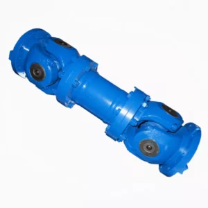
SWP-E Long Flexible Double Flange Universal Joint Couplings
-
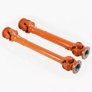
SWP-A Long Flexible Universal Joint Couplings
-
WGC Vertical Installation Drum Shape Gear Coupling
-
ML Plum Blossom Type Elastic Shaft Coupling
-
NGCLZ Drum Shape Gear Coupling with Brake Drum | Intermediate Shaft Type