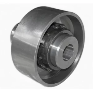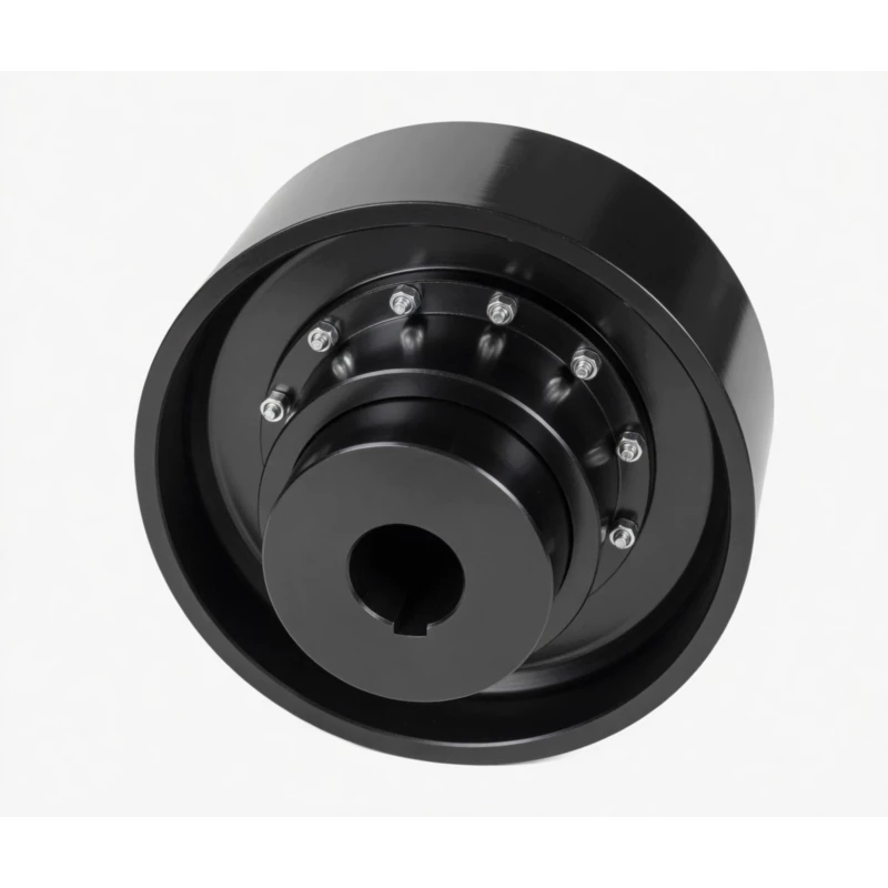
NGCLZ Drum Shape Gear Coupling with Brake Drum | Intermediate Shaft Type
NGCLZ drum shape gear coupling with integral brake drum and intermediate shaft per JB/T7003-93. 14 sizes, 355 N·m to 100,000 N·m, up to 4000 RPM. Brake drum D0 160–800 mm. Y, J1, Z1 bores. Axle withdrawal without shaft disturbance. For mine hoists and crane drives with distant shaft spacing.
NGCLZ Drum Shape Gear Coupling with Brake Drum — Intermediate Shaft Type
Three-in-one drive component: crowned-tooth gear coupling, integral shoe-brake drum, and intermediate shaft spacer — purpose-built for mine hoists, cranes, and heavy-drive systems with extended shaft spacing. Factory direct to Australia.
Product Overview
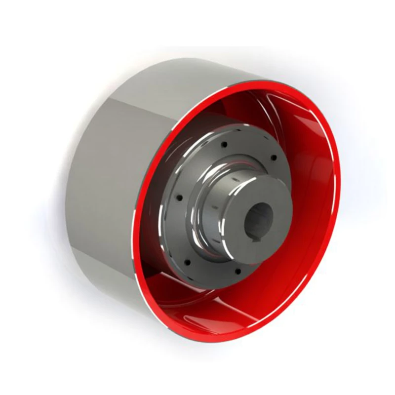
The NGCLZ drum shape gear coupling with brake drum is the intermediate-shaft variant of the NGCL series — a three-function power transmission component that simultaneously transmits torque through two crowned gear meshes, provides a precision-machined cylindrical brake drum surface (D0) for a shoe brake assembly, and incorporates an intermediate shaft spacer that bridges larger distances between the driving motor and driven gearbox or hoist drum.
Where the NGCL is used when motor and gearbox shaft ends are closely adjacent, the NGCLZ is the engineering choice when those shaft ends are separated by a meaningful distance — a common layout in mine hoists with headframe-mounted gearboxes, multi-stage gearbox drives on rolling mills, and crane hoist mechanisms where the motor is positioned offset from the drum drive. The intermediate shaft of the NGCLZ also serves a secondary maintenance function: by removing the spacer shaft, the motor or gearbox can be withdrawn axially for maintenance or replacement without disturbing the other machine's alignment.
GBC supplies NGCLZ couplings factory-direct to Australian mine operators, crane OEMs, and industrial equipment builders, with full material traceability documentation, dimensional inspection reports, and ISPM-15 compliant packing for seamless Australian customs clearance. Learn more about our complete range of industrial couplings for Australian applications.
Technical Definition and Working Principle
What the NGCLZ Is — and What Sets It Apart
The NGCLZ is a crowned-tooth gear coupling in the NGCL brake drum family, with the 'Z' suffix denoting the inclusion of an intermediate shaft (Zhong jian zhou in Chinese — the connecting spacer tube between the two half-couplings). The coupling consists of three main assemblies: two identical crowned-tooth hub halves (each machined with crowned external gear teeth and, on one half, the integral D0 brake drum flange), and a tubular intermediate shaft whose ends are fitted with internal gear sleeves that mesh with the respective crowned hubs.
This configuration creates two distinct gear meshes in series. Each mesh accommodates angular misalignment independently, so the NGCLZ's total angular compensation capacity is approximately twice that of a single-mesh coupling. This dual-mesh design is the key reason the NGCLZ is specified for drives where misalignment is expected to develop over time — as foundations settle, thermal growth occurs, or bearing wear accumulates across the drive train.
The critical differentiator from a straight-tooth gear coupling is the crowned (drum-shaped) tooth profile. A straight-tooth coupling transmits torque via a full-face line contact that concentrates stress at tooth edges when any angular misalignment is present. The crowned tooth creates a localised, self-centring Hertzian contact ellipse that migrates away from tooth edges under misalignment — distributing stress over a controlled contact area regardless of shaft angle. This fundamentally eliminates the destructive edge loading that causes premature spalling in straight-tooth designs.
The Three Functions of the NGCLZ
- Torque Transmission: Crowned gear teeth on both hub halves mesh with internal straight teeth in the sleeve flanges of the intermediate shaft. Torque flows: motor shaft → hub 1 crowned teeth → sleeve 1 internal teeth → intermediate shaft → sleeve 2 internal teeth → hub 2 crowned teeth → driven shaft.
- Brake Drum Surface: One coupling half (typically the motor side) is machined with an extended outer flange forming the D0 cylindrical brake drum surface. A shoe brake assembly clamps its brake blocks against this surface to decelerate or hold the drive train. D0 ranges from 160 mm to 800 mm across the NGCLZ series.
- Shaft Spacing: The intermediate shaft bridges the physical gap between motor and driven machine shaft ends. This enables equipment layouts that the close-coupled NGCL cannot serve, and facilitates axial withdrawal of either machine for maintenance without disturbing the other's mounting alignment.
Shaft Bore Combination Options
Unlike most gear couplings that offer a single bore type per half, the NGCLZ supports four factory-standard bore combination options. This flexibility allows a single NGCLZ size to serve a wide range of motor and gearbox shaft configurations without requiring custom adaptor hubs:
| Combination | Motor Side | Driven Side | Typical Use |
|---|---|---|---|
| Y / Y | Y cylindrical | Y cylindrical | Both shafts are standard cylindrical with keyway; most common general-purpose configuration |
| Y / J | Y cylindrical | J1 cylindrical (long) | Motor with standard Y shaft, gearbox or drum with longer J1 shaft; mixed motor/gearbox shaft standards |
| Z1 / J1 | Z1 conical taper (1:10) | J1 cylindrical | IEC motor with conical shaft end (Z1); preferred for high-cycle reversing or high-shock applications where keyless taper fit prevents fretting |
| J1 / J1 | J1 cylindrical (long) | J1 cylindrical (long) | Both shafts require long-engagement cylindrical bore; maximum bore engagement length on both sides |
Comparison with Other Coupling Types
| Feature | NGCLZ (this product) | Jaw Coupling | Disc Coupling | Rigid Flange |
|---|---|---|---|---|
| Integral Brake Drum | Yes — D0 shoe brake surface | No | No | No |
| Intermediate Shaft | Yes — standard feature | No | Spacer option available | No |
| Angular Misalignment | 1.0–1.5 deg per mesh (two meshes) | Up to 1 deg | Up to 1 deg | Near zero |
| Torque Range | 355 – 100000 KN·m | Low–Medium | Medium | High |
| Shock Load Tolerance | Excellent | Good (elastomer) | Poor | Transmitted fully |
| Axial Machine Withdrawal | Yes — remove spacer shaft | No | Spacer disc types only | No |
| Suitable for Hoisting / Crane | Yes — purpose-designed | No | No | No |
NGCL vs NGCLZ — Which Should You Choose?
Both the NGCL and NGCLZ are drum shape gear couplings with integrated brake drums, share the same torque ratings, and conform to JB/T7003-93. The decision between them comes down to drive train geometry and maintenance requirements. The table below clarifies when each is the right choice:
| Comparison Factor | NGCL (Close-Coupled) | NGCLZ (Intermediate Shaft) |
|---|---|---|
| Intermediate Shaft | No | Yes (standard) |
| Shaft-to-Shaft Gap | Short — shafts closely adjacent | Extended — shafts can be far apart |
| Gear Meshes | 1 pair | 2 pairs (higher misalignment) |
| Angular Misalignment | 1.0–1.5 deg (one mesh) | Up to 3 deg (two meshes combined) |
| Brake Drum (D0) | Integral on one half | Integral on one half |
| Machine Removal for Maintenance | Requires full coupling separation | Remove spacer shaft — motor or gearbox withdraws axially |
| Bore Combinations | Z1 or J1 / Y | Y/Y, Y/J, Z1/J1, J1/J1 |
| Overall Length | Shorter (B3) | Longer (B3 + intermediate shaft) |
| Choose When... | Shaft ends are closely spaced and B3 length fits the layout | Shaft ends are separated; maintenance withdrawal space is needed; higher misalignment is expected |
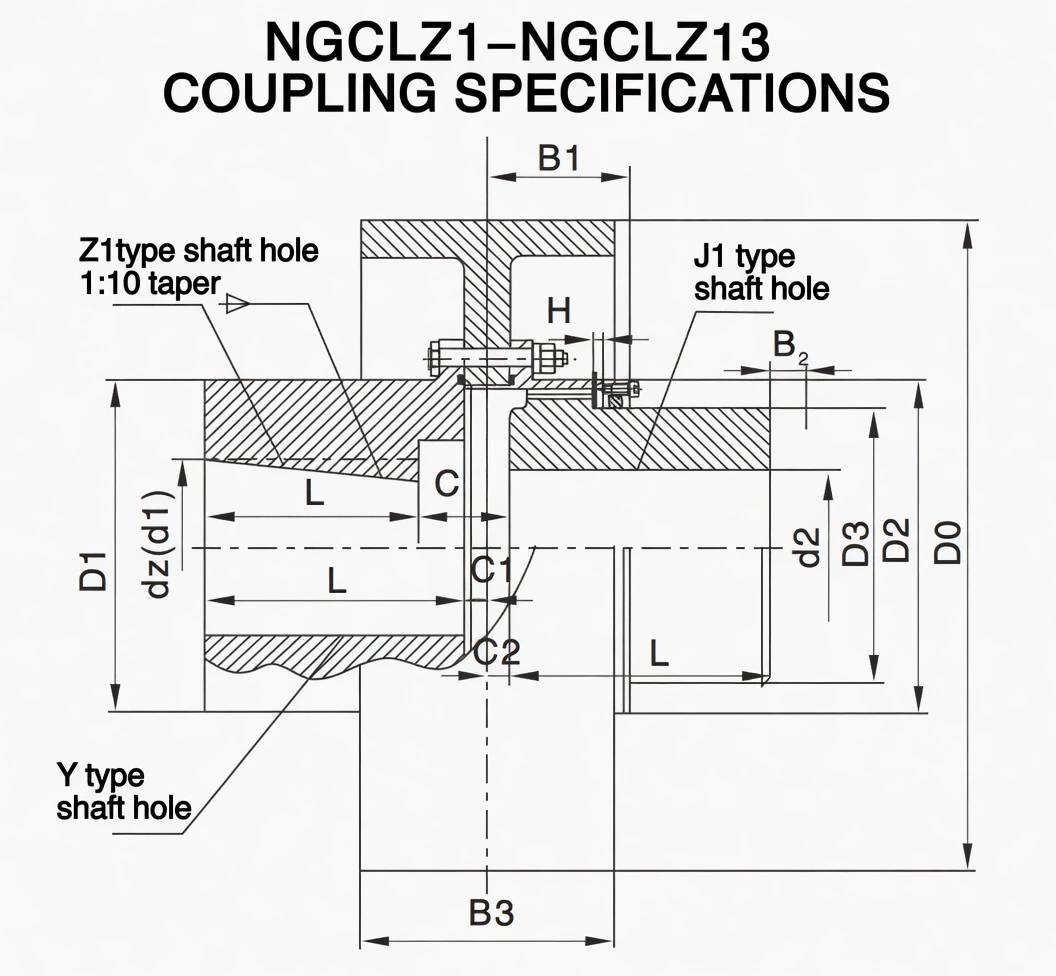
Specifications & Size Matrix — NGCLZ1 to NGCLZ14
All specifications are from the NGCLZ catalogue per JB/T7003-93. Dimensions in millimetres. D0 is the brake drum outer diameter. B2 is the seal replacement clearance dimension. Bracketed D0 values (e.g. 315/300) indicate both drum diameters are available — confirm with your shoe brake supplier before ordering.
NGCLZ1 – NGCLZ9 Specifications
| Type | Torque (KN·m) |
Speed (R/min) |
d1, d2 (mm) |
Y | J1, Z1 | D0 (brake) |
D | D1 | D2 | C | C1 | H | B | B1 | B2 | B3 | Inertia (Kg·m²) |
Weight (Kg) |
|---|---|---|---|---|---|---|---|---|---|---|---|---|---|---|---|---|---|---|
| NGCLZ1 | 355 | 4000 | 20, 22, 24 | 52 | 38 | 160 | 103 | 71 | 71 | 50 | 30 | 8 | 2 | 42 | 38 | 68 | 0.071 | 7.3 |
| 25, 28 | 62 | 44 | 0.072 | 7.4 | ||||||||||||||
| 30, 32, 35 | 82 | 60 | 0.076 | 8.4 | ||||||||||||||
| NGCLZ2 | 630 | 4000 | 25, 28 | 62 | 44 | 160 | 115 | 83 | 83 | 60 | 39 | 8 | 2 | 48 | 42 | 68 | 0.081 | 9.2 |
| 30, 32, 35, 38 | 82 | 60 | 0.084 | 10.3 | ||||||||||||||
| 40, 42, 45 | 112 | 84 | 0.088 | 10.5 | ||||||||||||||
| NGCLZ3 | 1000 | 3800 | 28 | 62 | 44 | 200 | 127 | 95 | 95 | 75 | 39 | 8 | 2 | 49 | 42 | 85 | 0.181 | 15.1 |
| 30, 32, 35, 38 | 82 | 60 | 0.184 | 16.3 | ||||||||||||||
| 40, 42, 45, 48, 50, 55 | 112 | 84 | 0.193 | 18.8 | ||||||||||||||
| NGCLZ4 | 1600 | 3800 | 38 | 82 | 60 | 200 | 149 | 116 | 116 | 90 | 46 | 8 | 2 | 53 | 42 | 85 | 0.225 | 19.8 |
| 40, 42, 45, 48, 50, 55, 56 | 112 | 84 | 0.242 | 23.3 | ||||||||||||||
| 60, 63, 65 | 142 | 107 | 0.296 | 26.8 | ||||||||||||||
| NGCLZ5 | 2800 | 3000 | 40–56 | 112 | 84 | 250 | 167 | 134 | 134 | 105 | 47 | 9 | 2.5 | 58 | 42 | 105 | 0.596 | 33.3 |
| 60–75 | 142 | 107 | 0.627 | 39 | ||||||||||||||
| NGCLZ6 | 4500 | 3000 | 45–56 | 112 | 84 | 250 | 187 | 153 | 153 | 125 | 52 | 9 | 2.5 | 59 | 42 | 105 | 0.72 | 40 |
| 60–75 | 142 | 107 | 0.776 | 46.4 | ||||||||||||||
| 80, 85, 90 | 172 | 132 | 0.837 | 53.2 | ||||||||||||||
| NGCLZ7 | 6300 | 2400 | 50, 55, 56 | 112 | 84 | 315 (300) | 204 | 170 | 170 | 140 | 52 | 9 | 2.5 | 63 | 42 | 132 | 1.178 | 51.8 |
| 60–75 | 142 | 107 | 1.254 | 59.8 | ||||||||||||||
| 80, 85, 90, 95 | 172 | 132 | 1.348 | 68.2 | ||||||||||||||
| 100 | 212 | 167 | 1.479 | 79.6 | ||||||||||||||
| NGCLZ8 | 9000 | 1900 | 55, 56 | 112 | 84 | 400 | 230 | 186 | 186 | 155 | 57 | 12 | 3 | 77 | 47 | 168 | 3.734 | 84 |
| 60–75 | 142 | 107 | 3.86 | 93.1 | ||||||||||||||
| 80, 85, 90, 95 | 172 | 132 | 3.996 | 104 | ||||||||||||||
| 100, 110 | 212 | 167 | 4.187 | 117 | ||||||||||||||
| NGCLZ9 | 14000 | 1500 | 60–75 | 142 | 107 | 500 | 256 | 212 | 212 | 180 | 64 | 13 | 3 | 47 | 47 | 210 | 9.43 | 133 |
| 80, 85, 90, 95 | 172 | 132 | 9.663 | 146 | ||||||||||||||
| 100, 110, 120, 125 | 212 | 167 | 9.997 | 164 | ||||||||||||||
| 130 | 252 | 202 | 10.3 | 182 |
NGCLZ10 – NGCLZ14 Specifications
| Type | Torque (KN·m) |
Speed (R/min) |
d1, d2 (mm) |
Y | J1, Z1 | D0 (brake) |
D | D1 | D2 | C | C1 | H | B | B1 | B2 (seal) |
B3 | Inertia (Kg·m²) |
Weight (Kg) |
|---|---|---|---|---|---|---|---|---|---|---|---|---|---|---|---|---|---|---|
| NGCLZ10 | 20000 | 1200 | 65, 70, 71, 75 | 142 | 107 | 630 (600) | 287 | 239 | 200 | 120 | 65 | 15 | 3.5 | 90 | 47 | 265 | 28.238 | 176 |
| 80, 85, 90, 95 | 172 | 132 | 28.509 | 190 | ||||||||||||||
| 100, 110, 120, 125 | 212 | 167 | 28.879 | 209 | ||||||||||||||
| 130, 140, 150 | 252 | 202 | 29.248 | 237 | ||||||||||||||
| NGCLZ11 | 31500 | 1050 | 70, 71, 75 | 142 | 107 | 710 (700) | 325 | 276 | 235 | 134 | 77 | 16 | 3.5 | 94 | 47 | 298 | 44.309 | 257 |
| 80, 85, 90, 95 | 172 | 132 | 44.825 | 275 | ||||||||||||||
| 100, 110, 120, 125 | 212 | 167 | 45.53 | 300 | ||||||||||||||
| 130, 140, 150 | 252 | 202 | 46.235 | 326 | ||||||||||||||
| 160, 170 | 302 | 242 | 47.08 | 357 | ||||||||||||||
| NGCLZ12 | 45000 | 1050 | 75 | 142 | 107 | 710 (700) | 362 | 313 | 270 | 164 | 94 | 17 | 4 | 104 | 49 | 298 | 47.88 | 306 |
| 80, 85, 90, 95 | 172 | 132 | 48.29 | 317 | ||||||||||||||
| 100, 110, 120, 125 | 212 | 167 | 49.52 | 351 | ||||||||||||||
| 130, 140, 150 | 252 | 202 | 50.25 | 384 | ||||||||||||||
| 160, 170, 180 | 302 | 242 | 52.22 | 425 | ||||||||||||||
| 190, 200 | 325 | 282 | 53.69 | 464 | ||||||||||||||
| NGCLZ13 | 63000 | 950 | 150 | 252 | 202 | 800 | 412 | 350 | 300 | 165 | 88 | 18 | 4.5 | 113 | 49 | 335 | 82.7 | 490 |
| 160, 170, 180 | 302 | 242 | 84.7 | 544 | ||||||||||||||
| 190, 200, 220 | 352 | 282 | 86.67 | 596 | ||||||||||||||
| NGCLZ14 | 100000 | 950 | 170, 180 | 302 | 242 | 800 | 462 | 420 | 335 | 209 | 92 | 20 | 5.5 | 157 | 63 | 335 | 99.1 | 670 |
| 190, 200, 220 | 352 | 282 | 102.2 | 736 | ||||||||||||||
| 240, 250 | 410 | 330 | 105.9 | 785 |
Notes: B2 is the dimension for seal replacement clearance. Bracketed D0 values (e.g. 315/300, 630/600, 710/700) indicate both drum diameters are available for that size — confirm with your shoe brake supplier. Bore sizes shown in parentheses are not recommended for new designs.
Custom Bore, Intermediate Shaft Length & Brake Drum Size Available
Non-standard bore diameters, Z1 taper configurations, modified intermediate shaft lengths, and alternative D0 dimensions are all achievable to drawing. Contact our engineering team with your drive train layout for a custom assessment within 24 hours.
Industries & Applications in Australia
The NGCLZ is deployed wherever the NGCL's functions are needed — braked hoisting, crane drives, and heavy machinery requiring controlled stopping — but with the added requirement that motor and gearbox shaft ends are separated by a distance that the close-coupled NGCL cannot bridge. This includes headframe-mounted hoist gearboxes, multi-motor crane drives, and long-span industrial drives throughout Australia's mining, port, and steel industries.
Mine Hoists & Winders — Headframe Drives
Equipment: Drum hoists, Koepe winders, shaft-sinking winches, man-riding hoists, production skip hoists.
In many Australian underground mines, the motor and hoist gearbox are located on opposite sides of the headframe structural platform, creating a shaft-to-shaft gap that requires the NGCLZ intermediate shaft variant. The NGCLZ's spacer also enables the motor to be withdrawn axially along the shaft line for rewinding or replacement without moving the gearbox — a critical maintenance advantage when access in a headframe is constrained by structural steelwork. The D0 brake drum provides the braking surface required by AS 3777 and WA, QLD, and NSW mine safety regulations.
Overhead Cranes — Long-Span Hoist Drives
Equipment: Ladle cranes, EOT cranes with extended centre distances, gantry cranes, portal cranes, floating cranes.
Large overhead crane hoist mechanisms often position the drive motor and hoist drum gearbox at different heights or lateral positions within the crab structure, creating a shaft-to-shaft gap that the NGCLZ intermediate shaft bridges. The NGCLZ's four bore combination options (Y/Y, Y/J, Z1/J1, J1/J1) accommodate the variety of motor and gearbox shaft configurations found across crane OEM designs in the Australian market. Learn more about our full industrial coupling range for crane applications.
Port Equipment & Ship Loading Systems
Equipment: Shiploaders, ship unloaders, stacker-reclaimer slew and luff drives, grab crane hoists, container terminal gantries.
At bulk export terminals in Port Hedland, Dampier, Newcastle, and Hay Point, port equipment operates continuously under high torque with regular emergency stop requirements. The NGCLZ's intermediate shaft allows equipment designers to position the motor and gearbox with the optimum mechanical advantage on the drive train — without being constrained by the motor-to-gearbox gap limit of a close-coupled NGCL.
Rolling Mills & Steel Plant Machinery
Equipment: Rolling mill main drives with integrated runout braking, coiler and uncoiler drives, crane traverse and hoist drives within steel plant.
Steel mill drive trains operate at high torques with severe shock loading from each rolling pass. The NGCLZ's two gear meshes provide double the angular misalignment compensation of the NGCL — critical in rolling mills where foundation thermal distortion causes progressive misalignment during extended campaign runs. The intermediate shaft also simplifies roll-change maintenance by allowing gearbox withdrawal without disturbing the motor mounting.
Heavy-Duty Winches & Anchor Handling Equipment
Equipment: Mooring winches, anchor windlasses, trawl winches, tensioning winches, pipeline tensioners.
Marine winch drives on vessels servicing Australia's offshore oil and gas sector (North West Shelf, Bass Strait) require the Z1/J1 bore combination for secure motor-shaft connections under high cyclic load reversal. The NGCLZ intermediate shaft allows the winch drum shaft and motor shaft to be positioned at the optimal mechanical distance for the vessel's winch room layout, while the integral brake drum provides the required holding brake for mooring operations.
Technical Advantages — Why Crowned Tooth Outperforms Straight Tooth
Higher Misalignment Tolerance — Especially Critical in Australian Mining
The NGCLZ's two crowned gear meshes provide a combined angular misalignment capacity of approximately 2–3 degrees — twice that of a single-mesh coupling. On Australian mine hoists in the Pilbara and Bowen Basin, where headframe foundations on expansive soils can shift by millimetres per year, this double tolerance ensures the coupling continues operating through progressive misalignment cycles without the edge loading that would destroy a straight-tooth coupling within months. The intermediate shaft also absorbs relative displacement between the two shaft ends that a rigid coupling would transmit as bending stress into the motor and gearbox bearings.
Longer Service Life Under Shock Loads and Brake Applications
Mine hoists and crane hoist drives experience two types of severe loading simultaneously: torsional shock during load pickup, and combined torsional plus braking stress during emergency stops. The NGCLZ is designed to handle both simultaneously — the crowned tooth absorbs torsional shock peaks by distributing contact stress over a controlled Hertzian ellipse, while the D0 brake drum is dimensioned to carry full braking torque without yielding, even during emergency stop under full load. Straight-tooth couplings in the same service see edge loading on both functions compounding the damage rate, typically failing at 30–50% of the crowned-tooth equivalent's service life.
Reduced Bearing Loads
A misaligned straight-tooth coupling transmits bending moments into both motor and gearbox bearings at 2x running frequency. In hoist applications, these forces add to the inherent radial loads from rope tension and drum weight. The NGCLZ's self-centering crowned teeth minimise the misalignment-induced component of these loads — and the intermediate shaft provides an additional degree of freedom that further reduces the bending moment transmitted to shaft bearings. Australian crane operators report a measurable reduction in drive-end motor bearing replacement frequency after switching from straight-tooth to NGCLZ-type couplings in comparable hoist applications.
Lower Maintenance Frequency — Valuable in Remote Australian Operations
NGCLZ lubrication intervals reach 6–12 months under standard operating conditions. For mine hoists at remote Pilbara or Goldfields sites, where maintenance crews access the headframe by elevated work platforms and specialist rope-access technicians, reducing the frequency of coupling maintenance directly reduces work-at-height exposure risk and the associated permit-to-work burden. The NGCLZ's intermediate shaft also means that motor or gearbox removal for unrelated maintenance does not require disturbing the coupling seals — the spacer shaft is simply removed, leaving both half-couplings in place and preserving their lubrication.
Suitable for High-Speed Applications
Smaller NGCLZ sizes (NGCLZ1 through NGCLZ6) are rated to 3000–4000 RPM — appropriate for direct 4-pole motor coupling on 50 Hz supplies. The intermediate shaft is balanced as part of the coupling assembly, and the crowned tooth profile generates significantly less vibration excitation at speed than straight-tooth equivalents under misalignment. This makes the NGCLZ suitable for VSD-driven hoist motors where smooth operation across the full speed range is required by the control system.
Manufacturing & Quality Assurance
Manufacturing Highlights
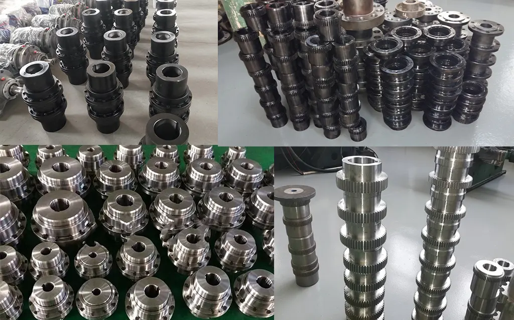
NGCLZ couplings are manufactured from forged alloy steel blanks — 42CrMo4 for NGCLZ8 and above, 45# carbon steel for smaller sizes. The D0 brake drum surface and the crowned gear teeth are machined from the same forging, maintaining concentricity between the gear axis and the brake drum braking surface to within 0.05 mm total runout. This concentricity is critical for even shoe brake wear: any eccentricity causes the brake blocks to contact unevenly around the drum circumference, accelerating lining wear and generating vibration during braking.
Crowned tooth profiles are generated on CNC gear hobbing machines with dedicated crowned tooling, achieving DIN Class 7 accuracy. The intermediate shaft is turned and bored to H7 tolerance on both end faces, with gear sleeves pressed or shrunk onto each end and then machined as an assembly to ensure sleeve-to-sleeve runout is within specification. The assembled NGCLZ is spin-checked for rotational balance on a dynamic balancing machine before painting.
The brake drum surface receives a dedicated finish-turning pass after heat treatment to achieve Ra 1.6–3.2 micrometres — the surface roughness specification required for consistent shoe brake operation and controlled brake lining wear-in.
Quality Control Flow
Certifications
ISO 9001:2015 quality management system covers the complete NGCLZ manufacturing process. CE marking applies to applicable sizes. Products manufactured to JB/T7003-93. Full documentation packages — material mill certificates with heat number traceability, heat treatment records, hardness test reports, D0 runout inspection records, and dimensional reports — are standard for every shipment and support Australian mining safety compliance submissions under WA, QLD, and NSW mining regulations.
Why Source Your NGCLZ Couplings from GBC?
Australian Safety Standards Expertise
We provide documentation structured for Australian mine safety and crane compliance, including AS 3777 (Winding Installations), AS 4991 (Hoisting Equipment), and state mining safety regulation requirements. Our engineers understand the coupling certification requirements in Australian engineering change management processes and can prepare technical files to support regulatory submissions.
15+ Years Exporting to Australia
Since 2010 GBC has supplied NGCLZ brake drum couplings to mine hoist OEMs, crane manufacturers, and port equipment builders across Australia. We have shipped to every major Australian port and to remote mine sites via road-heavy transport in WA, QLD, and NT. We have zero customs rejection incidents across 15 years of Australian export — ISPM-15 packing and AQIS biosecurity compliance are standard on every order.
English-Speaking Engineering Team
Our engineers respond to technical queries in English, review your drive train layout drawings, confirm coupling selection against safety factor requirements, and verify bore and keyway specifications against your motor and gearbox data sheets. We have experience with the terminology and calculation conventions used by Australian mechanical engineers, including service factor selection per AS 1418 for crane drives and hoisting applications.
Flexible MOQ — From Single Pieces
NGCLZ couplings are available from one piece. Remote mine sites that need a single replacement NGCLZ on short notice are as welcome as OEM projects ordering a fleet of identical units. Standard catalogue sizes ship within 15–20 working days ex-works. We can also hold consignment stock for high-volume Australian customers to support planned maintenance schedules.
OEM & Custom Design Capability
Custom intermediate shaft lengths, non-standard D0 diameters, modified B3 overall lengths, hardened and ground brake drum surfaces, and special bore combinations beyond the standard catalogue are all achievable. We have designed and manufactured custom NGCLZ variants for Australian crane OEMs and mine hoist rebuilders, with drawing-to-delivery lead times of 25–35 working days for most custom configurations. Contact us with your drawing.
Factory Direct — Full Traceability
GBC is the manufacturer. Every NGCLZ ships with heat number-traceable material certificates, heat treatment records, and hardness test reports — the documents Australian safety auditors expect to see for hoist and crane coupling inspections. No trading company markups, no traceability chain gaps, no uncertainty about manufacturing origin.
Application Case Studies
Case 1: Underground Gold Mine Winder — Kalgoorlie, WA
Customer Profile: An underground gold producer in the Eastern Goldfields operating a 2.8 MW friction winder at 980 m depth, with the drive motor and gearbox on opposite sides of the headframe crossbeam — a shaft-to-shaft gap of 380 mm that the NGCL standard length could not bridge.
Challenge: The existing coupling arrangement used a close-coupled NGCL with a separate stub shaft adaptor to bridge the gap. The adaptor introduced eccentricity between the brake drum and gear axis, causing brake shoe chatter, accelerated shoe wear, and vibration on the winder structure. The vibration was triggering the winder's out-of-balance protection system, causing nuisance trips approximately twice per month.
Solution: We supplied a custom NGCLZ10 (20,000 KN·m, 120 mm bore Z1/J1 combination, D0 = 630 mm) with a 380 mm intermediate shaft length to match the headframe geometry exactly. A single integrated unit replaced the NGCL-plus-adaptor arrangement, eliminating the source of eccentricity.
Result: Winder brake vibration dropped by 73% at the first post-installation measurement. No nuisance brake trips have been recorded in 22 months since installation. Brake shoe life increased from approximately 8 months to 18+ months — an estimated annual saving of AUD $35,000 in brake lining and shoe replacement costs.
Case 2: Shiploader Luffing Drive Upgrade — Port of Dampier, WA
Customer Profile: A major iron ore port terminal at Dampier operating two high-capacity shiploaders handling 90 Mt per annum combined throughput.
Challenge: The luffing drive on each shiploader used two motors driving a common gearbox through separate gear couplings, with each motor shaft end separated from the gearbox input by 450–500 mm due to the structural layout of the luffing machinery deck. Repeated tooth failures on the existing couplings were causing unplanned outages of 8–12 hours, at a throughput cost of approximately AUD $800,000 per outage at prevailing iron ore prices.
Solution: We supplied 4x NGCLZ11 couplings (31,500 KN·m, 150 mm bore, J1/J1 combination, D0 = 710 mm) per shiploader — two per motor shaft — with custom 450 mm intermediate shaft lengths. Full material certification and hardness reports were provided for the port's engineering compliance file.
Result: Zero coupling failures in 26 months of continuous operation across all four units on both shiploaders. Port engineering management estimated that the elimination of coupling-related outages over the 26-month period preserved throughput revenue of approximately AUD $4.8 million compared to the previous failure rate.
Case 3: Crane Hoist Refurbishment Programme — Queensland Steel Mill
Customer Profile: An integrated steelworks in South East Queensland operating 24 overhead cranes in the melt shop and casthouse, each with hoist capacities from 50 to 320 tonnes.
Challenge: A fleet-wide coupling refurbishment programme identified that 18 of the 24 cranes used oversized close-coupled NGCL couplings fitted with custom adaptor shafts to bridge motor-to-gearbox gaps — a legacy solution from the original equipment build that was adding an unnecessary alignment-sensitive joint to each drive train. Coupling and adaptor failures were causing an average of 3.2 unplanned hoist outages per crane per year across the fleet.
Solution: Working from the crane OEM's engineering drawings, we supplied 18 purpose-sized NGCLZ couplings (NGCLZ8 to NGCLZ12, torques 9,000–45,000 KN·m) with intermediate shaft lengths matched to the actual motor-to-gearbox gap in each crane model. The J1/J1 bore combination was standardised across the fleet for parts interchangeability where shaft sizes allowed.
Result: Fleet-wide hoist coupling failures reduced from 57 per year (pre-refurbishment) to 4 per year (minor seal replacements only) in the first 18 months post-installation — a 93% reduction. Total maintenance hours attributed to hoist coupling interventions dropped by 88%. The steelworks maintenance manager cited the refurbishment programme as delivering an estimated AUD $2.3 million annual benefit in avoided downtime and maintenance labour.
Frequently Asked Questions
What is an NGCLZ drum shape gear coupling?
The NGCLZ is a crowned-tooth gear coupling combining three functions: torque transmission through two crowned gear meshes, an integral D0 brake drum surface for a shoe brake assembly, and an intermediate shaft spacer that bridges the gap between two shaft ends. Conforming to JB/T7003-93, the 14-size series covers 355–100,000 KN·m with D0 brake drums of 160–800 mm.
What is the difference between NGCLZ and NGCL?
Both are brake drum gear couplings with the same D0 sizes and torque ratings. The NGCL is close-coupled (no spacer). The NGCLZ has an intermediate shaft that bridges a larger motor-to-gearbox gap, provides double the angular misalignment compensation (two meshes vs one), enables axial machine withdrawal for maintenance, and supports four bore combination options vs the NGCL's two.
What shaft bore combinations are available for NGCLZ?
Four standard combinations: Y/Y (both sides cylindrical Y type), Y/J (Y on one side, J1 long cylindrical on the other), Z1/J1 (1:10 conical taper on one side, J1 on the other), and J1/J1 (both sides J1 long cylindrical). The Z1/J1 combination is preferred for IEC motors with conical shaft ends in high-shock or reversing drive applications where keyless taper connection provides superior fretting resistance.
What does the B2 dimension mean in NGCLZ specifications?
B2 is the axial clearance dimension for seal replacement. When a coupling seal reaches end-of-life and needs replacement during planned maintenance, B2 defines the axial space required to remove and fit the replacement seal cartridge without disassembling the entire coupling. This is an important practical dimension for maintenance planning on mine hoists and crane drives.
Can I get a custom intermediate shaft length for NGCLZ?
Yes. The intermediate shaft length can be customised to your specific motor-to-gearbox gap dimension. Standard catalogue B3 lengths may not match your drive train geometry — particularly on older equipment or custom-engineered installations. Send us your drive train layout drawing with the required shaft-end separation distance and we will design the appropriate intermediate shaft. Custom shaft lengths typically add 10–15 working days to the standard lead time.
What documentation is available for Australian safety compliance?
We supply material certificates with heat number traceability, heat treatment records, Rockwell hardness test certificates for the gear teeth and brake drum surface, D0 concentricity runout measurement records, dimensional inspection reports, and manufacturing declarations of conformity. For mine hoists under WA, QLD, and NSW mine safety legislation, our engineering team can prepare a technical submission package to support equipment acceptance by the relevant authority. Contact us with your specific documentation requirements.
Specify Your NGCLZ Coupling & Brake System
Send us your torque requirement, shaft-to-shaft gap, D0 brake drum size, bore combination, and application details. Our engineering team confirms the right NGCLZ configuration and provides a competitive factory-direct quotation within 24 hours — with full compliance documentation for Australian safety submissions.
|
English-speaking engineering team
|
sales@australia-drive.com
GBC — Factory-direct NGCLZ drum shape gear couplings with brake drum and intermediate shaft for Australian hoisting, crane, and heavy industrial applications since 2010.
NGCLZ drum shape gear coupling with integral brake drum and intermediate shaft per JB/T7003-93. 14 sizes, 355 N·m to 100,000 N·m, up to 4000 RPM. Brake drum D0 160–800 mm. Y, J1, Z1 bores. Axle withdrawal without shaft disturbance. For mine hoists and crane drives with distant shaft spacing.