NGCL Drum Shape Gear Coupling with Brake Drum
NGCL drum shape gear coupling with integral cylindrical brake drum for shoe brakes per JB/T7003-93. 14 sizes, 355 N·m to 100,000 N·m, up to 4000 RPM. Brake drum D0 160–800 mm. Y, J1, Z1 bores. Preferred for mine hoists, crane drives, and inclined conveyor emergency stops in Australia.
NGCL Drum Shape Gear Coupling with Brake Drum
Crowned-tooth gear coupling with integrated brake drum for shoe brakes — engineered for hoisting, crane, and heavy-drive applications requiring simultaneous power transmission and braking. Factory direct to Australia.
Product Overview
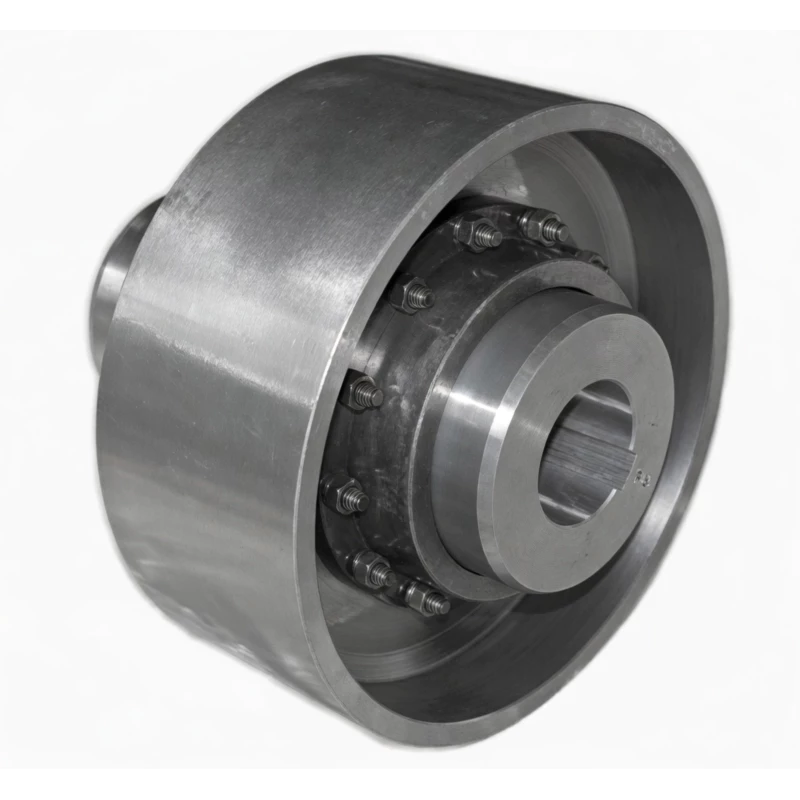
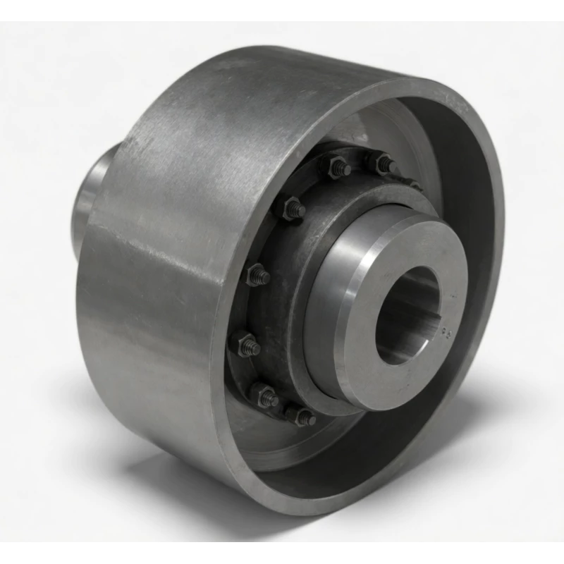
The NGCL drum shape gear coupling is a two-in-one power transmission component: it simultaneously acts as a crowned-tooth gear coupling connecting two shafts and provides an integral cylindrical brake drum surface for a mating shoe brake assembly. This combined function makes the NGCL the standard solution for drive trains that require both precise torque transmission and reliable braking — particularly in hoisting machinery, overhead cranes, mine winders, and heavy conveyor systems where holding or stopping a loaded drive train is a safety requirement.
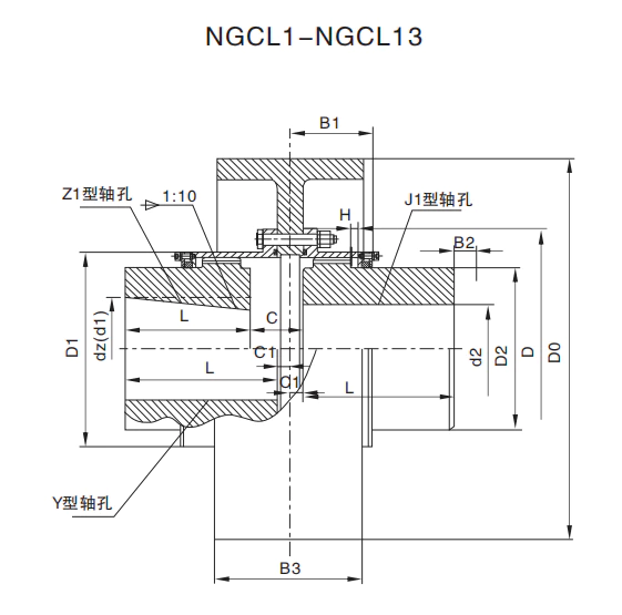
The coupling conforms to JB/T7003-93 and covers 14 sizes from NGCL1 to NGCL14, spanning a torque range from 355 KN·m to 100,000 KN·m. The brake drum diameter D0 — which is the critical dimension for shoe brake selection — ranges from 160 mm to 800 mm. Both Z1 conical taper shaft bores and J1/Y cylindrical shaft bores are supported, providing compatibility with IEC standard motor shaft ends as well as gearbox output shafts.
At GBC, we manufacture and export NGCL couplings factory-direct to Australian crane builders, mining equipment suppliers, and industrial machinery OEMs. Every coupling ships with full material certificates, dimensional inspection records, and ISPM-15 compliant packing for Australian customs.
Technical Definition and Working Principle
What Makes the NGCL Unique
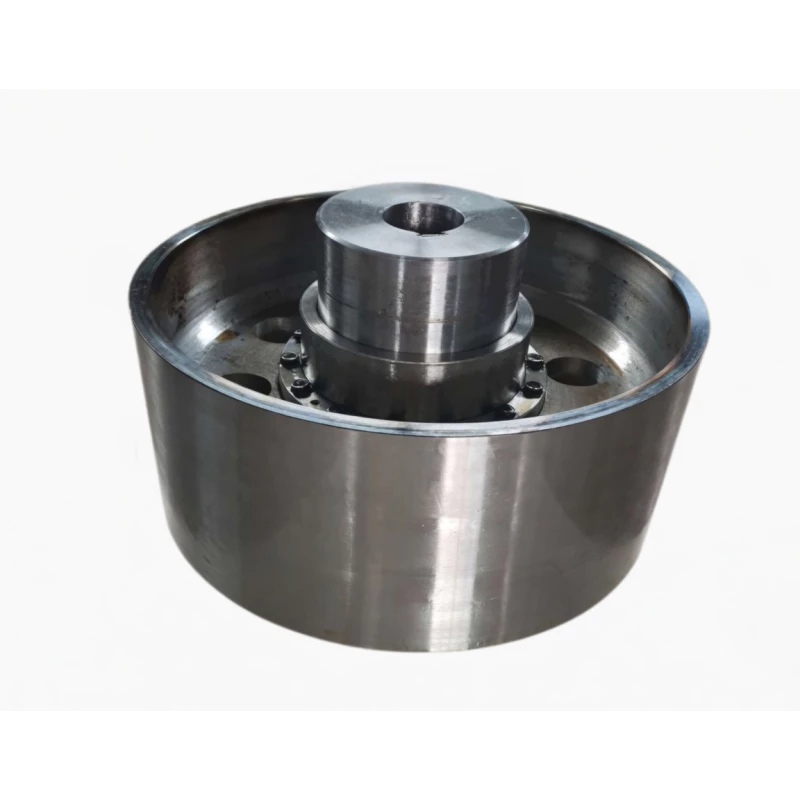
Among drum shape gear couplings, the NGCL stands alone in integrating a brake drum directly into the coupling body. One coupling half (typically the motor side, accepting the Z1 taper bore) is machined with an extended outer flange that forms the cylindrical braking surface — the D0 brake drum. A shoe brake unit (block brake) mounts adjacent to the coupling and clamps its brake blocks against this drum surface to retard or hold the drive train.
This integrated design eliminates the need for a separate brake drum component mounted elsewhere on the shaft. It reduces the total drive train length, eliminates the alignment requirement between a separate brake drum and its shaft, and provides a single, structurally coherent component that carries both torque transmission and braking stresses through the same forged steel body.
The gear coupling function of the NGCL uses crowned (drum-shaped) tooth geometry on both external gear hubs. This is the critical differentiator from a straight-tooth gear coupling: the crowned profile creates a self-centering Hertzian contact near the tooth centre rather than a line contact at the tooth edges. Under shaft misalignment — unavoidable in real-world drive trains due to installation tolerances, thermal expansion, and foundation movement — the crowned tooth maintains controlled contact stress distribution while a straight-tooth coupling generates destructive edge loading that causes premature spalling and failure.
Brake Drum Integration — How It Works
The D0 dimension is the outer diameter of the integral brake drum surface machined on the larger coupling half. When a shoe brake is specified to work with an NGCL coupling, the brake is sized using D0 as the drum diameter — exactly as it would be for a standalone drum brake. The shoe brake's pivot geometry, contact arc, and hydraulic or spring actuator force are all calculated around D0 to achieve the required braking torque.
The structural integrity of the integrated drum is designed to handle the combined loading of:
- Full rated torque transmission through the gear mesh simultaneously with full braking torque from the shoe brake — the most demanding loading case that occurs during emergency stop under full load.
- Cyclic thermal loading from repeated brake applications, managed through the alloy steel composition and heat treatment specification of the drum surface.
- Radial and bending forces from the shoe brake clamping load, which acts perpendicular to the shaft axis and imposes bending stress on the drum flange.
Crowned Tooth Geometry and Misalignment Compensation
The NGCL gear mesh accommodates angular misalignment of 1.0 to 1.5 degrees, radial parallel offset, and axial displacement. The axial sliding capability is particularly important in hoisting applications where thermal expansion of the motor shaft and gearbox shafts during continuous operation would otherwise impose axial thrust on both the motor bearing and the gearbox input bearing. The crowned tooth absorbs this axial growth within the mesh without generating thrust forces.
Comparison with Other Coupling Types
| Feature | NGCL Drum Gear + Brake | Gear Coupling (No Brake) | Jaw Coupling | Disc Coupling |
|---|---|---|---|---|
| Integrated Brake Drum | Yes — D0 surface for shoe brake | No — separate drum required | No | No |
| Torque Capacity (this range) | 355 – 100000 KN·m | High | Low–Medium | Medium |
| Angular Misalignment | 1.0 – 1.5 deg per mesh | 1.0 – 1.5 deg | Up to 1 deg | Up to 1 deg |
| Shock Load Tolerance | Excellent | Excellent | Good | Poor |
| Drive Train Length | Compact — drum integral | Requires separate brake drum | Compact | Compact |
| Suitable for Hoisting/Crane Use | Yes — purpose-designed | Only with separate brake | No | No |
| Z1 Taper Bore Support | Yes | Depends on type | Limited | No |
Specifications & Size Matrix — NGCL1 to NGCL14
All specifications below are from the NGCL product catalogue per JB/T7003-93. All dimensions in millimetres. D0 is the brake drum outer diameter — the critical dimension for shoe brake selection. The series spans 14 sizes covering torques from 355 KN·m to 100,000 KN·m.
NGCL1 – NGCL7 Specifications
| Type | Torque (KN·m) |
Speed (R/min) |
dz range (mm) |
d1, d2 (mm) |
Y | J1, Z1 | D0 (brake drum) |
D | D1 | D2 | C | C1 | H | B | B1 | B2 | B3 | Inertia (Kg·m²) |
Weight (Kg) |
|---|---|---|---|---|---|---|---|---|---|---|---|---|---|---|---|---|---|---|---|
| NGCL1 | 355 | 4000 | 20 – 35 | 20, 22, 24 | 52 | 38 | 160 | 103 | 71 | 50 | 30 | 8 | 2 | 56 | 42 | 38 | 68 | 0.07 | 7 |
| 25, 28 | 62 | 44 | 0.07 | 7.3 | |||||||||||||||
| 30, 32, 35 | 82 | 60 | 0.071 | 8 | |||||||||||||||
| NGCL2 | 630 | 4000 | 25 – 45 | 25, 28 | 62 | 44 | 160 | 115 | 83 | 60 | 36 | 8 | 2 | 68 | 48 | 42 | 68 | 0.079 | 9 |
| 30, 32, 35, 38 | 82 | 60 | 0.08 | 9.7 | |||||||||||||||
| 40, 42, 45 | 112 | 84 | 0.083 | 11 | |||||||||||||||
| NGCL3 | 1000 | 3800 | 30 – 55 | 28 | 62 | 44 | 200 | 127 | 95 | 75 | 41 | 8 | 2 | 70 | 49 | 42 | 85 | 0.181 | 14.6 |
| 30, 32, 35, 38 | 82 | 60 | 0.184 | 15.2 | |||||||||||||||
| 40, 42, 45, 48, 50, 55, 56 | 112 | 84 | 0.187 | 17 | |||||||||||||||
| NGCL4 | 1600 | 3800 | 40 – 65 | 38 | 82 | 60 | 200 | 149 | 116 | 90 | 41 | 8 | 2 | 74 | 53 | 42 | 85 | 0.225 | 18.6 |
| 40, 42, 45, 48, 50, 55, 56 | 112 | 84 | 0.237 | 21.4 | |||||||||||||||
| 60, 63, 65 | 142 | 107 | 0.246 | 23.8 | |||||||||||||||
| NGCL5 | 2800 | 3000 | 45 – 75 | 40–56 | 112 | 84 | 250 | 167 | 134 | 105 | 48 | 8 | 2.5 | 84 | 58 | 42 | 105 | 0.58 | 31.8 |
| 60, 63, 65, 70, 71, 75 | 142 | 107 | 0.609 | 34.4 | |||||||||||||||
| NGCL6 | 4500 | 3000 | 50 – 90 | 45, 48, 50, 55, 56 | 112 | 84 | 250 | 187 | 153 | 125 | 49 | 9 | 2.5 | 85 | 59 | 42 | 105 | 0.714 | 37.2 |
| 60, 63, 65, 70, 71, 75 | 142 | 107 | 0.754 | 38.5 | |||||||||||||||
| 80, 85, 90 | 172 | 132 | 0.795 | 47.6 | |||||||||||||||
| NGCL7 | 6300 | 2400 | 60 – 100 | 50, 55, 56 | 112 | 84 | 315 (300) | 204 | 170 | 140 | 53 | 9 | 2.5 | 93 | 63 | 42 | 132 | 1.17 | 48.8 |
| 60, 63, 65, 70, 71, 75 | 142 | 107 | 1.234 | 55.2 | |||||||||||||||
| 80, 85, 90, 95 | 172 | 132 | 1.299 | 61.8 | |||||||||||||||
| 100 | 212 | 167 | 1.388 | 71.1 |
NGCL8 – NGCL14 Specifications
| Type | Torque (KN·m) |
Speed (R/min) |
dz range (mm) |
d1, d2 (mm) |
Y | J1, Z1 | D0 (brake drum) |
D | D1 | D2 | C | C1 | H | B | B1 | B2 | B3 | Inertia (Kg·m²) |
Weight (Kg) |
|---|---|---|---|---|---|---|---|---|---|---|---|---|---|---|---|---|---|---|---|
| NGCL8 | 9000 | 1900 | 70 – 110 | 55, 56 | 112 | 84 | 400 | 230 | 186 | 155 | 64 | 12 | 3 | 112 | 77 | 47 | 168 | 3.747 | 80.7 |
| 60, 63, 65, 70, 71, 75 | 142 | 107 | 3.841 | 90 | |||||||||||||||
| 80, 85, 90, 95 | 172 | 132 | 3.939 | 96.5 | |||||||||||||||
| 100, 110 | 212 | 167 | 4.072 | 108 | |||||||||||||||
| NGCL9 | 14000 | 1500 | 80 – 130 | 60, 63, 65, 70, 71, 75 | 142 | 107 | 500 | 256 | 212 | 180 | 71 | 13 | 3 | 119 | 80 | 47 | 210 | 9.427 | 128 |
| 80, 85, 90, 95 | 172 | 132 | 9.605 | 138 | |||||||||||||||
| 100, 110, 120, 125 | 212 | 167 | 9.847 | 151 | |||||||||||||||
| 130 | 252 | 202 | 10.109 | 167 | |||||||||||||||
| NGCL10 | 20000 | 1200 | 80 – 150 | 65, 70, 71, 75 | 142 | 107 | 630 (600) | 287 | 239 | 200 | 65 | 15 | 3.5 | 120 | 90 | 47 | 265 | 28.238 | 176 |
| 80, 85, 90, 95 | 172 | 132 | 28.509 | 190 | |||||||||||||||
| 100, 110, 120, 125 | 212 | 167 | 28.879 | 209 | |||||||||||||||
| 130, 140, 150 | 252 | 202 | 29.248 | 237 | |||||||||||||||
| NGCL11 | 31500 | 1050 | 100 – 170 | 70, 71, 75 | 142 | 107 | 710 (700) | 325 | 276 | 235 | 77 | 16 | 3.5 | 134 | 94 | 47 | 298 | 44.309 | 257 |
| 80, 85, 90, 95 | 172 | 132 | 44.825 | 275 | |||||||||||||||
| 100, 110, 120, 125 | 212 | 167 | 45.53 | 300 | |||||||||||||||
| 130, 140, 150 | 252 | 202 | 46.235 | 326 | |||||||||||||||
| 160, 170 | 302 | 242 | 47.08 | 357 | |||||||||||||||
| NGCL12 | 45000 | 1050 | 100 – 200 | 75 | 142 | 107 | 710 (700) | 362 | 313 | 270 | 94 | 17 | 4 | 164 | 104 | 49 | 298 | 47.88 | 306 |
| 80, 85, 90, 95 | 172 | 132 | 48.29 | 317 | |||||||||||||||
| 100, 110, 120, 125 | 212 | 167 | 49.52 | 351 | |||||||||||||||
| 130, 140, 150 | 252 | 202 | 50.25 | 384 | |||||||||||||||
| 160, 170, 180 | 302 | 242 | 52.22 | 425 | |||||||||||||||
| 190, 200 | 352 | 282 | 53.69 | 464 | |||||||||||||||
| NGCL13 | 63000 | 950 | 150 – 220 | 150 | 252 | 202 | 800 | 412 | 350 | 300 | 88 | 18 | 4.5 | 165 | 113 | 49 | 335 | 82.7 | 490 |
| 160, 170, 180 | 302 | 242 | 84.7 | 544 | |||||||||||||||
| 190, 200, 220 | 352 | 282 | 86.67 | 596 | |||||||||||||||
| NGCL14 | 100000 | 950 | 170 – 220 | 170, 180 | 302 | 242 | 800 | 462 | 420 | 335 | 92 | 20 | 5.5 | 209 | 157 | 63 | 335 | 99.1 | 670 |
| 190, 200, 220 | 352 | 282 | 102.2 | 736 | |||||||||||||||
| 240, 250 | 410 | 330 | 105.9 | 785 |
Note: D0 values in parentheses (e.g. 315/300, 630/600, 710/700) indicate that both drum diameters are available for the same coupling size. Confirm D0 with your shoe brake supplier before ordering. Shaft hole length J1 type is recommended; Z1 type is conical taper 1:10.
Custom Bore & Brake Drum Specifications Available
Need a non-standard bore, Z1 taper ratio, or a specific brake drum surface finish? Our engineering team accommodates custom specifications including alternative D0 diameters, hardened drum surfaces, and special keyway profiles. Contact us with your drawing or brake-coupling system specification.
Industries & Applications in Australia
The NGCL drum shape gear coupling with brake drum is purpose-built for drive trains where stopping and holding the load is a safety-critical function. In Australia, this coupling type is deployed across some of the most demanding industrial environments — from iron ore mine hoists in the Pilbara to port ship loaders on the Queensland coast.
Mine Hoists & Winders
Equipment: Drum hoists, Koepe winders, man-riding hoists, skip hoists, Blair multi-rope hoists.
Mine hoists are the most safety-critical application for the NGCL. AS 3777 (Winding Installations) and the Mine Safety Acts of WA, QLD, and NSW require engineered braking systems capable of stopping and holding the hoist under specified load and speed conditions. The NGCL's integral brake drum provides the standardised braking surface for the spring-applied, hydraulically-released shoe brakes that are mandatory on Australian mine winders. The crowned tooth gear coupling simultaneously compensates for motor-to-gearbox misalignment caused by foundation movement in deep-level operations.
Overhead Travelling Cranes & Gantry Cranes
Equipment: EOT cranes, ladle cranes, coil transfer cranes, container gantry cranes, ship-to-shore cranes.
Crane hoist mechanisms are required by AS 4991 (Hoisting Equipment) to incorporate fail-safe brakes on all motions. The NGCL provides the brake drum surface for the hoist drum drive's holding brake — typically a spring-applied shoe brake that engages automatically on power loss. Using an integrated NGCL rather than a separate brake drum eliminates an alignment-sensitive component from the drive train, reducing the risk of coupling-to-drum eccentricity that causes vibration complaints on crane hoists. Our drum shape gear coupling range covers the full size range for crane hoist drives.
Port & Bulk Materials Handling
Equipment: Ship loaders, ship unloaders, stacker-reclaimers, bucket wheel excavators, shiploader luffing drives.
Port terminals at Newcastle, Hay Point, Dalrymple Bay, Dampier, and Port Hedland depend on bulk materials handling equipment that operates continuously under high loads. Luffing drives and slew drives on ship loaders require positive braking to hold the boom under wind load. The NGCL's robust alloy steel brake drum handles the thermal cycling associated with frequent load-holding operations without the drum surface crazing that occurs with inferior material specifications.
Metallurgy & Steel Mills
Equipment: Rolling mill main drives with runout braking, ladle turret drives, continuous caster drives, coiler drives.
Steel mill drives combine extremely high transmitted torques with the need for rapid, controlled deceleration to precise stopping positions. The NGCL handles the simultaneous demands of peak torque transmission and emergency braking in a single compact unit, reducing drive train length in mill housings where space is constrained. The crowned tooth geometry tolerates the angular misalignment that develops as mill stands thermally distort during continuous casting campaigns.
Winches & Tension Drives
Equipment: Offshore mooring winches, anchor winches, trawl winches, tensioning capstans, pipeline laying tensioners.
Marine and offshore winch drives on vessels operating out of Fremantle, Darwin, and Gladstone rely on NGCL-type couplings where the same shaft must provide both drive and braking. The Z1 taper bore option on the NGCL is particularly valued in marine applications where the keyless taper connection resists the fretting and loosening that cylindrical keyed bores suffer under the cyclic shock loads of wave-action mooring operations.
Technical Advantages — Why Crowned Tooth Outperforms Straight Tooth
Higher Misalignment Tolerance — Critical for Australian Mining
Mine hoist foundations in the Pilbara and Hunter Valley experience ongoing ground movement due to ore extraction and expansive subsoils. This causes slow, progressive shaft misalignment in hoist drive trains. The NGCL's crowned tooth accommodates up to 1.5 degrees of angular misalignment continuously — without any increase in gear tooth contact stress. Straight-tooth gear couplings in the same applications develop destructive edge loading at misalignments above 0.3–0.5 degrees, leading to spalling failures within months on sites where a crowned-tooth NGCL runs for years.
Longer Service Life Under Shock Loads
Crane hoist drives experience peak torque spikes when a load is picked up from rest or when the hoist engages after a slack rope condition. These instantaneous torque spikes can reach 3–5x the nominal rated torque. The crowned tooth distributes this peak load across a Hertzian contact ellipse rather than concentrating it at tooth edges — significantly reducing peak contact stress. This is why NGCL couplings routinely outlast straight-tooth alternatives by 2–4x in crane hoist applications where shock loading is frequent.
Reduced Bearing Loads
A misaligned straight-tooth gear coupling generates bending moments that impose cyclic radial forces at 2x running frequency on motor and gearbox bearings. In hoist applications, these forces combine with the inherent radial loads from the rope tension — accelerating bearing fatigue. The NGCL's self-centering crowned tooth minimises these misalignment-induced forces, extending motor and gearbox bearing life and reducing the frequency of bearing replacement on height-access drive train components.
Lower Maintenance Frequency
Lubrication intervals for NGCL couplings are typically 6–12 months under normal operating conditions. In mine hoist applications where the coupling is located in a headframe above the shaft collar, access for maintenance requires work-at-height procedures and crane access — making each maintenance event expensive and time-consuming. The NGCL's extended lubrication interval, compared to 3–6 months for straight-tooth equivalents, directly reduces the number of high-risk maintenance events per year.
Axial Float for Thermal Expansion
Large hoist motors and gearboxes experience significant thermal expansion during continuous operation — particularly during extended production periods in hot Australian climates. The NGCL's crowned teeth slide axially within the sleeve to accommodate this growth, preventing the build-up of axial thrust loads on motor and gearbox bearings. This is a critical advantage over rigid couplings and disc couplings, which transmit full thermal expansion forces to adjacent bearings and can cause premature failure of otherwise properly sized bearing assemblies.
Manufacturing & Quality Assurance
Manufacturing Process
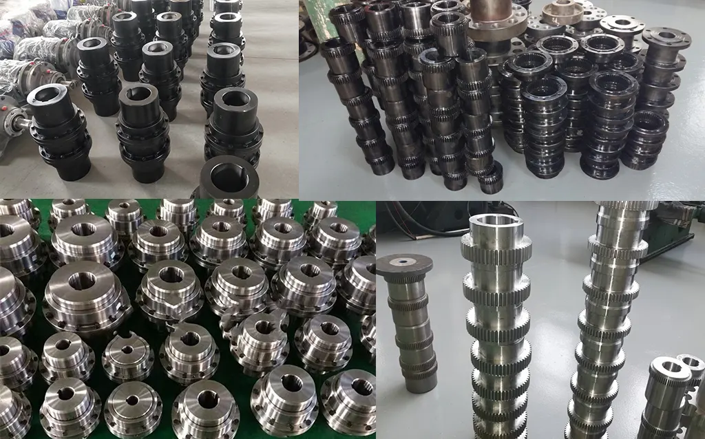
Every NGCL coupling starts as a high-quality forged alloy steel blank — 42CrMo4 for NGCL8 and above, 45# carbon steel for smaller sizes. The brake drum surface (D0) and gear teeth are machined from the same forging, ensuring concentricity between the coupling gear centre and the brake drum centre. This is critical: any eccentricity between the gear axis and the brake drum axis causes vibration and uneven shoe wear during braking.
The crowned tooth profiles are generated on CNC gear hobbing machines with dedicated crowned-tooth tooling, achieving DIN Class 7 accuracy or better. Tooth flanks are carburised and quenched to achieve surface hardness of HRC 58–62 with core hardness of HRC 30–35. The brake drum surface receives a separate finish-turning pass after heat treatment to achieve the surface roughness specification required for effective shoe brake operation — typically Ra 1.6 to 3.2 micrometres.
Quality Control Flow
Inspection Equipment
Our QC laboratory operates CNC gear profile testers for crowned tooth geometry verification, Rockwell hardness testers for post-quench surface hardness confirmation, coordinate measuring machines (CMM) for dimensional verification of D0 concentricity relative to bore axis, surface profilometers for brake drum surface roughness measurement, optical emission spectrometers for raw material chemistry verification, and magnetic particle inspection (MPI) equipment for crack detection on safety-critical components.
Certifications & Standards
ISO 9001:2015 certification covers the complete NGCL manufacturing process. Products are manufactured to JB/T7003-93. For Australian customers subject to mine safety legislation (WA Mine Safety and Inspection Regulations, QLD Mining and Quarrying Safety and Health Act, NSW Work Health and Safety (Mines and Petroleum Sites) Regulation), we provide full documentation packages including material certificates, heat treatment records, dimensional inspection reports, and hardness test certificates to support equipment integrity management systems.
Why Source Your NGCL Couplings from GBC?
Australian Safety Standards Awareness
We understand the regulatory environment for hoist and crane couplings in Australia. This includes AS 3777 (Winding Installations), AS 4991 (Hoisting Equipment), and state mining safety regulations. Our documentation packages are structured to support Australian compliance audits, and our engineers can discuss coupling selection in the context of brake system design calculations required by these standards.
15+ Years of Australian Export Experience
Since 2010, GBC has supplied brake drum gear couplings to Australian mine hoist OEMs, crane manufacturers, and industrial equipment rebuilders. We have shipped NGCL couplings to sites in WA, QLD, NSW, SA, and the NT. We understand AQIS biosecurity requirements, ISPM-15 packing, and Australian port-to-site logistics — including remote mine site delivery coordination.
Engineering Support in English
Our technical team supports coupling selection calculations, bore and keyway specification, D0 brake drum sizing for shoe brake compatibility, and documentation preparation. All communication is in English, and our engineers are familiar with the terminology and calculation methods used by Australian mechanical engineers — including service factor selection per AS 1418 series for crane drives.
Flexible MOQ from Single Pieces
NGCL couplings are available from single-piece orders — important for maintenance replacement scenarios where a mine site needs an exact replacement without committing to a large stock holding. Bulk pricing applies for project orders of 3 or more units of the same size and bore specification. Lead times for standard catalogue sizes are 15–20 working days ex-works.
OEM & Custom Capability
Beyond standard JB/T7003-93 dimensions, we manufacture to customer drawings. Non-standard D0 diameters, modified B3 overall lengths, hardened and ground brake drum surfaces, and special bore configurations are all achievable. We have produced custom NGCL variants for Australian crane OEMs on repeat basis with drawing-to-delivery lead times of 20–30 working days.
Factory Direct — Full Traceability
GBC manufactures every NGCL in our own facility. Every coupling ships with a factory test certificate, material certificate with heat number traceability, and hardness test report — documents required for engineering integrity management under Australian mining safety regulations. No intermediaries, no grey-market stock, no traceability gaps.
Application Case Studies
Case 1: Skip Hoist Coupling Replacement — Western Australian Gold Mine
Customer Profile: A mid-tier underground gold producer in the Kalgoorlie region operating a 3.2 MW drum hoist for skip winding at 1,100 metres depth.
Challenge: The existing brake drum gear coupling (competitor product) was exhibiting tooth spalling after 14 months in service. Vibration analysis confirmed 2x-frequency excitation consistent with misalignment-induced coupling forces. The D0 brake drum surface was showing uneven wear patterns, compromising braking consistency — a safety-critical issue requiring shutdown. Replacement involved a complex work-at-height operation in the headframe.
Solution: We supplied an NGCL11 coupling (31,500 KN·m rated torque, 130 mm bore, Z1 taper bore on the motor side, D0 = 710 mm) with a hardened and ground brake drum surface finish to Ra 1.6 for improved shoe brake performance. Material certificates and hardness test reports were provided to support the site's engineering change management process.
Result: After 28 months in continuous service, the replacement coupling shows no tooth wear indicators on vibration monitoring. Brake shoe wear rate reduced by approximately 30% due to the improved drum surface geometry. The site's maintenance planner extended the coupling inspection interval from 12 months to 18 months, based on condition monitoring data.
Case 2: Ladle Crane Hoist Drive — Queensland Aluminium Smelter
Customer Profile: A major aluminium smelter in central Queensland operating 8 ladle cranes in the casthouse, each lifting molten metal ladles at up to 120 tonnes.
Challenge: The hoist drum drive couplings were being replaced every 10–12 months due to accelerated tooth wear. Investigation revealed that the high ambient temperatures in the casthouse (ambient up to 60 degrees Celsius) were causing lubricant degradation in straight-tooth couplings within 4–5 months — well before the scheduled 12-month lube change. Tooth contact stress was then running dry, causing rapid abrasive wear.
Solution: We supplied 8x NGCL9 couplings (14,000 KN·m, 110 mm bore, D0 = 500 mm) with a high-temperature lithium complex grease filling rated for continuous operation to 180 degrees Celsius. The crowned tooth geometry generates significantly less heat than the straight-tooth design at the same misalignment, extending the effective lubricant life.
Result: After 24 months, no coupling replacements have been required on any of the 8 cranes. The maintenance team confirmed that tooth wear at 24 months was within acceptable limits per the manufacturer's inspection criteria. Estimated saving versus the previous replacement cycle: AUD $128,000 in parts and labour across the 8-crane fleet over the two-year period.
Case 3: Shiploader Luffing Drive — Port of Newcastle
Customer Profile: A coal export terminal at the Port of Newcastle operating two coal shiploaders handling 30 million tonnes per annum.
Challenge: The shiploader luffing drive couplings were failing due to the high cyclic load reversal from wind-induced boom movement. Each time wind load reversed the boom direction, the drive train experienced a torque reversal that caused tooth impact in the misaligned straight-tooth couplings. Brake shoe wear was also accelerated by the drum surface waviness caused by eccentricity in the separate brake drum assembly.
Solution: We supplied 4x NGCL10 couplings (20,000 KN·m, 140 mm bore, D0 = 630 mm) per shiploader — replacing the existing coupling plus separate brake drum with a single integrated NGCL unit. The integral machined drum eliminated the eccentricity issue that had caused brake shoe wear.
Result: Brake shoe life increased by approximately 65% following installation, eliminating two unplanned brake inspections per shiploader per year. The couplings have operated for 30 months without replacement. The terminal engineering team specified NGCL as the standard coupling for all future luffing drive refurbishments across the site. Contact us to discuss your port or materials handling application.
Frequently Asked Questions
What is an NGCL drum shape gear coupling?
The NGCL is a crowned-tooth gear coupling with an integrated brake drum machined into one coupling half. It transmits torque between two shafts while providing a D0 cylindrical surface for a shoe brake assembly. Conforming to JB/T7003-93, the 14-size series covers torques from 355 KN·m to 100,000 KN·m with brake drum diameters from 160 mm to 800 mm.
What is the brake drum (D0) used for on the NGCL?
D0 is the outer diameter of the cylindrical braking surface machined into one coupling half. A shoe brake assembly clamps its brake blocks against this surface to decelerate or hold the drive train. When specifying a shoe brake for an NGCL coupling, use D0 as the brake drum diameter in the brake torque calculation. The D0 dimension is the same for both bore variants within each NGCL size (where two D0 values are listed, both are available — confirm with your brake supplier which is required).
What shaft bore types does the NGCL accept?
The NGCL accepts Z1 (1:10 conical taper bore, on the dz side — typically motor side), J1 (cylindrical shaft with keyway, longer engagement), and Y (cylindrical with keyway, standard length). The dz range column in the specification tables shows which Z1 taper bore sizes are available for each NGCL size. The d1, d2 columns show the cylindrical shaft bore options for the opposite half.
What is the difference between NGCL and NGCLZ?
The NGCL is a close-coupled variant where both coupling halves connect directly to adjacent shaft ends. The NGCLZ adds an intermediate shaft between the two halves, allowing the coupling to bridge a greater distance between the driving and driven shafts while retaining the integrated brake drum. The NGCLZ is specified when motor-to-gearbox shaft spacing exceeds what the standard NGCL overall length (B3) can accommodate.
Can you supply custom bore or non-standard D0 dimensions?
Yes. We supply custom Z1 taper bores, non-standard cylindrical bore diameters, special keyway profiles, and alternative D0 brake drum diameters to customer drawings. For non-standard D0, we assess the structural impact on the coupling half and confirm feasibility before accepting the order. Custom orders typically require 20–30 working days depending on size and complexity. Send your drawing to sales@australia-drive.com for an assessment.
What documentation is available for Australian compliance purposes?
We provide material certificates with heat number traceability, heat treatment records, dimensional inspection reports, Rockwell hardness test certificates, and manufacturing declarations of conformity. For mine safety applications in WA, QLD, or NSW where coupling certification is required under mining safety legislation, our engineering team can prepare a technical file to support your equipment acceptance process. Contact our team to discuss specific documentation requirements for your application.
Specify Your NGCL Coupling & Brake System
Tell us your torque requirement, shaft dimensions, D0 brake drum size, and application details. Our engineering team confirms the right NGCL size and provides a competitive, factory-direct quotation within 24 hours — with full documentation support for Australian safety compliance.
|
English-speaking engineering team
|
sales@australia-drive.com
GBC — Factory-direct NGCL drum shape gear couplings with brake drum for Australian hoisting, crane, and industrial applications since 2010.
NGCL drum shape gear coupling with integral cylindrical brake drum for shoe brakes per JB/T7003-93. 14 sizes, 355 N·m to 100,000 N·m, up to 4000 RPM. Brake drum D0 160–800 mm. Y, J1, Z1 bores. Preferred for mine hoists, crane drives, and inclined conveyor emergency stops in Australia.
Related products
-
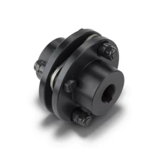
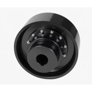
DJM Type Single Flexible Diaphragm Coupling
-
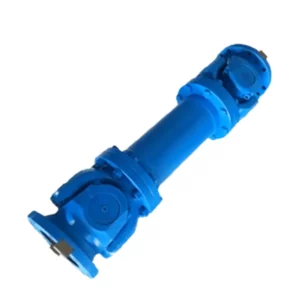
SWP-D Long Non-Flexible Universal Joint Couplings
-
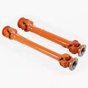
SWP-A Long Flexible Universal Joint Couplings
-
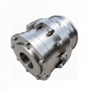
WGC Vertical Installation Drum Shape Gear Coupling
-
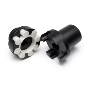
ML Plum Blossom Type Elastic Shaft Coupling
-
NGCLZ Drum Shape Gear Coupling with Brake Drum | Intermediate Shaft Type