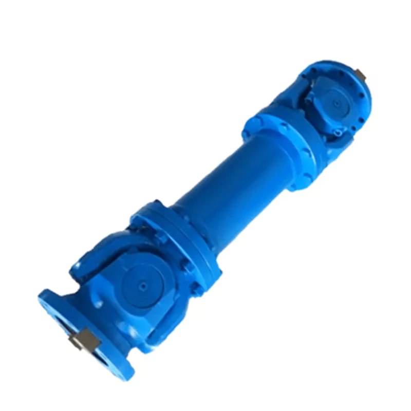
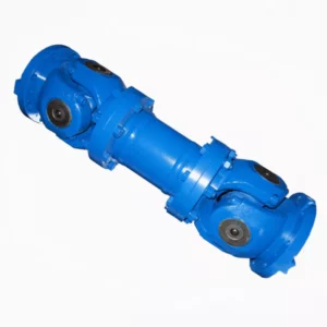
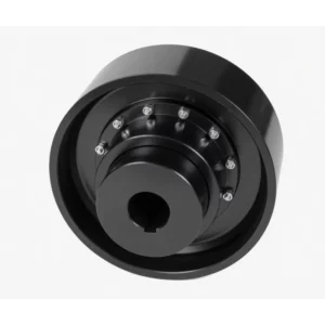
SWP-D Long Non-Flexible Universal Joint Couplings
The SWP-D Long Non-Flexible Universal Joint Coupling delivers extended shaft span coverage (Lmin 430–1980 mm) with a fixed-length rigid intermediate body — no telescoping sleeve. Covering gyration diameters 160–640 mm and nominal torques 16–1 250 kN·m at ≤10° fold angle, SWP-D is specified for long-span fixed-geometry drives including industrial fan drives, mining hoists, and pump station drivetrains where angular compensation is needed but axial shaft movement is absent.
SWP-D Long Non-Flexible Universal Joint Couplings — Product Overview
The SWP-D Long Non-Flexible Universal Joint Coupling occupies a precise niche in the SWP family: it combines the extended shaft span of SWP-A with the fixed-length rigid body of SWP-C. Where SWP-A adds a telescoping sleeve to accommodate axial movement, and SWP-C achieves compactness by shortening the body, SWP-D extends the intermediate tube to span large centre-to-centre distances — without any sliding interface.
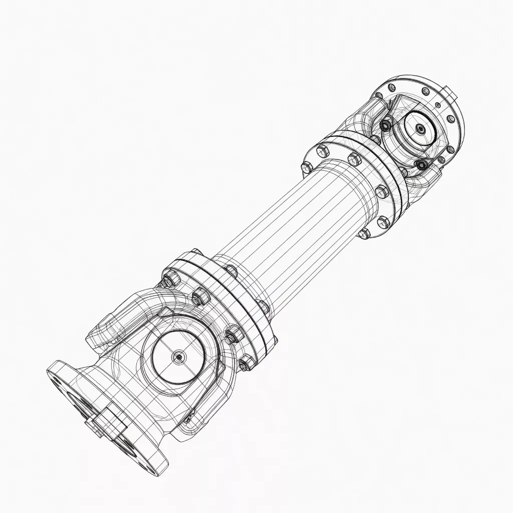
The coupling transmits torque through two Hooke's joint assemblies linked by a precision-aligned fixed-length tube. Fold angle compensation of ≤10° is maintained across the full torque range of 16 to 1 250 kN·m. The split axletree bearing housing on both yoke ends enables in-situ spider replacement without shaft removal — the maintenance hallmark of the entire SWP series. With gyration diameters from 160 mm to 640 mm and Lmin values of 430 mm to 1 980 mm, SWP-D covers long-span industrial drivetrains across mining hoists, large industrial fan drives, rolling mill main pinion lines, and long-distance pump station drives.
Structural advantages of the fixed long tube: Unlike SWP-A, the SWP-D intermediate body carries no internal sliding components — this eliminates the stick-slip friction that occurs in telescoping sleeves under axial preload and avoids the fretting wear on spline teeth that can occur in telescoping types subjected to vibration without proper lubrication. For long-span, high-speed drives, this results in measurably smoother torque transmission and lower maintenance frequency for the intermediate section.
Australian market relevance: Large industrial fan drives in Australian power stations and process plants frequently involve motor-to-gearbox spans of 800–1 500 mm where the SWP-D fixed long tube provides an engineering-appropriate solution. Mining hoist drivetrains with drum-to-gearbox distances exceeding SWP-C Lmin values also benefit from SWP-D's extended range, providing angular compensation for foundation settlement without axial compliance that could interact with the hoist drum's axial position control.
D3 dimension: Like SWP-A and SWP-E, the SWP-D specification includes a D3 dimension (intermediate tube outer diameter), which is relevant for coupling guard and clearance calculations in the installation design.
Technical Specifications
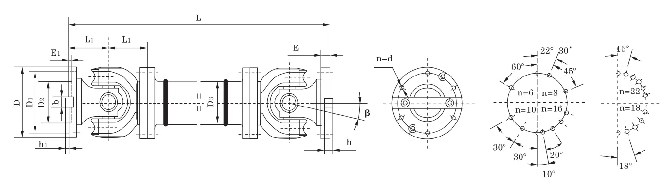
| Type | D (mm) | Tn (kN·m) | Tf (kN·m) | β | Lmin (mm) | D1 js11 | D2 H7 | D3 | E | E1 | b×h | h1 | L1 | n–d | I Lmin (kg·m²) | ΔI/100mm | G Lmin (kg) | ΔG/100mm |
|---|---|---|---|---|---|---|---|---|---|---|---|---|---|---|---|---|---|---|
| SWP160D | 160 | 16 | 8 | ≤10 | 430 | 140 | 95 | 114 | 15 | 4 | 20×12 | 6 | 85 | 6–13 | 0.09 | 0.0059 | 35 | 2.1 |
| SWP180D | 180 | 20 | 10 | ≤10 | 474 | 155 | 105 | 121 | 15 | 4 | 24×14 | 7 | 95 | 6–15 | 0.16 | 0.0072 | 47 | 2.3 |
| SWP200D | 200 | 31.5 | 16 | ≤10 | 544 | 175 | 125 | 127 | 17 | 5 | 28×16 | 8 | 110 | 8–15 | 0.28 | 0.0114 | 67 | 3.4 |
| SWP225D | 225 | 40 | 20 | ≤10 | 636 | 196 | 135 | 152 | 20 | 5 | 32×18 | 9 | 130 | 8–17 | 0.53 | 0.029 | 94 | 6.6 |
| SWP250D | 250 | 63 | 31.5 | ≤10 | 690 | 218 | 150 | 168 | 25 | 5 | 40×25 | 12.5 | 135 | 8–19 | 0.91 | 0.0407 | 140 | 7.3 |
| SWP285D | 285 | 90 | 45 | ≤10 | 760 | 245 | 170 | 194 | 27 | 7 | 40×30 | 15 | 150 | 8–21 | 1.91 | 0.0702 | 206 | 9.4 |
| SWP315D | 315 | 140 | 63 | ≤10 | 860 | 280 | 185 | 219 | 32 | 7 | 40×30 | 15 | 170 | 10–23 | 3.39 | 0.1144 | 271 | 12.0 |
| SWP350D | 350 | 180 | 90 | ≤10 | 940 | 310 | 210 | 245 | 35 | 8 | 50×32 | 16 | 185 | 10–23 | 5.35 | 0.1663 | 355 | 13.6 |
| SWP390D | 390 | 250 | 112 | ≤10 | 1060 | 345 | 235 | 273 | 40 | 8 | 70×36 | 18 | 205 | 10–25 | 10.54 | 0.2695 | 501 | 18.0 |
| SWP435D | 435 | 355 | 160 | ≤10 | 1180 | 385 | 255 | 299 | 42 | 10 | 80×40 | 20 | 235 | 16–28 | 18.56 | 0.3645 | 825 | 20.0 |
| SWP480D | 480 | 450 | 224 | ≤10 | 1360 | 425 | 275 | 351 | 47 | 12 | 90×45 | 22.5 | 265 | 16–31 | 31.69 | 0.7028 | 1144 | 28.0 |
| SWP550D | 550 | 710 | 315 | ≤10 | 1460 | 492 | 320 | 402 | 50 | 12 | 100×45 | 22.5 | 290 | 16–31 | 51.45 | 1.1842 | 1589 | 35.7 |
| SWP600D | 600 | 1000 | 500 | ≤10 | 1840 | 544 | 380 | 450 | 55 | 15 | 90×55 | 27.5 | 360 | 22–34 | 83.53 | 1.7159 | 2243 | 40.5 |
| SWP640D | 640 | 1250 | 630 | ≤10 | 1980 | 575 | 385 | 480 | 60 | 15 | 100×60 | 30 | 385 | 18–38 | 135.6 | 2.308 | 3140 | 48.3 |
Note: D=315mm, L=900mm → SWP315D×900. All dimensions mm. SWP-D has no Ls column (fixed length). D3 = intermediate tube OD for guard clearance design. ΔI and ΔG are incremental values per 100 mm length increase.
Industry Applications
Large Industrial Fan Drives — Power & Process Plants
Working condition: High-speed operation (500–1000 rpm), continuous duty, critical service, precise shaft alignment over long spans. Fan shaft and motor shaft separated by gearbox with centre distances up to 1 800 mm.
Why SWP-D: The fixed long tube spans the motor-to-gearbox or gearbox-to-fan distance without the sliding friction of telescoping types. Stiffer intermediate body suppresses shaft whip at operating speed. Angular compensation accommodates settling of fan casing foundations without transmitting bending loads to fan shaft bearings.
Customer benefit: Fan bearing MTBF extended versus rigid spacer couplings; vibration levels measurably lower than with telescoping sleeve types in high-speed service.
️ Mining Hoist Drivetrains — Fixed Drum Geometry
Working condition: Cyclic loading with high peak torques during acceleration, drum position axially fixed by thrust bearing arrangement, long motor-to-drum shaft span on large winders.
Why SWP-D: Hoist drum axial position is controlled by the drum shaft's dedicated thrust bearing — no axial compliance is desired in the drivetrain. SWP-D provides angular compensation for motor and gearbox foundation settlement (common over years of operation) while keeping drum axial position under full thrust bearing control. The long fixed tube bridges standard motor-to-gearbox spacings without modification.
Customer benefit: Drum position integrity maintained; no coupling-induced axial loads on drum bearings; lower maintenance frequency versus telescoping type.
Long-Span Pump Station Drives
Working condition: Remote location, minimal maintenance access, motor and pump separated by large reducer or gearbox with extended shaft spans.
Why SWP-D: Rural and remote pump station drivetrains across Australian water infrastructure and mineral processing circuits often have motor-to-pump shaft spans beyond SWP-C Lmin capacity. SWP-D extends the reach while maintaining fixed-axial-position integrity demanded by pump shaft thrust bearings.
Customer benefit: Single-coupling solution for long spans without intermediate bearing housing; reduced maintenance obligation at remote sites.
⚙️ Rolling Mill Pinion Stands — Auxiliary Line Shafts
Working condition: Long auxiliary line shaft from main gearbox to pinion stand, moderate speed, fixed rolling mill frame geometry.
Why SWP-D: Where the SWP-A's telescoping feature is unnecessary (rolling mill line shaft positions are fixed by the mill housing), the SWP-D provides the required long span more economically and with lower inertia — benefiting drive sizing and motor acceleration performance.
Customer benefit: Lower drivetrain inertia improves rolling mill speed response; no spline maintenance between scheduled overhauls.
How to Choose: SWP-D vs SWP-A vs SWP-C
The SWP-D is the most frequently misspecified type in the SWP range, primarily because engineers default to SWP-A for any long-span application. The key discriminator is whether axial movement occurs in service — if not, SWP-D is technically superior and more cost-effective than SWP-A for fixed-span applications.
| Feature | SWP-D (Long Non-Flex) | SWP-A (Long Flex) | SWP-C (Short Non-Flex) | SWP-F (Long Big Flex) |
|---|---|---|---|---|
| Body Length | Long (430–1980 mm) | Long (660–2685 mm) | Short (340–1540 mm) | Long (770–2920 mm) |
| Telescoping (Axial) | ❌ None | ✅ 50–230 mm | ❌ None | ✅ 150–380 mm (large) |
| Angular Capacity | ≤10° | ≤10° | ≤10° | ≤10° |
| Rotational Inertia vs A | Lower (no sleeve) | Reference | Lowest | Higher |
| Lubrication Points | 2 (spiders only) | 3 (spiders + sleeve) | 2 (spiders only) | 3 (spiders + sleeve) |
| Ideal For | Long fixed-span drives | Long spans with axial float | Short fixed-span drives | Long spans, large axial float |
Sizing Guidance for Long-Span Installations
Critical speed check: For SWP-D, the fixed tube acts as a rotating shaft — at long spans, the first critical speed must exceed maximum operating speed by at least 30% safety factor. Critical speed Nc ≈ (4.73/L²) × √(EI/ρA), where L is tube length, E is Young's modulus, I is second moment of area, ρ is density, and A is cross-section area. For SWP-D sizes above D315 at spans over 1.2 m, request our critical speed confirmation before ordering for high-speed applications (>800 rpm).
Foundation settlement allowance: Specify the maximum expected angular misalignment change over the equipment lifetime (foundation settlement, bearing wear, frame distortion). SWP-D accommodates ≤10°; for sites with expected foundation movement above 5° cumulative, plan for periodic realignment rather than relying on the coupling's full angular capacity continuously.
⚠️ Critical Mistakes to Avoid with SWP-D
- Applying SWP-D where thermal shaft growth exists: Motor shafts in high-ambient industrial environments can grow 1–3 mm axially at operating temperature. SWP-D transmits this growth directly as axial force to connected bearings — potentially loading thrust faces not designed for coupling-induced loads. Always confirm thermal growth is zero or absorbed by dedicated thrust bearings before specifying non-flex type.
- Exceeding critical speed without analysis: Long SWP-D tubes at high speed can operate near or above their first bending critical speed. For any combination of D≤285 and L>1.0 m at speeds above 1000 rpm, a critical speed calculation is mandatory.
- Treating SWP-D and SWP-A as interchangeable: Both are long types, but SWP-D has lower inertia and no axial compliance. Swapping SWP-A for SWP-D in an existing installation where the SWP-A was compensating shaft thermal growth will cause immediate bearing overload.
Unsure whether SWP-D or SWP-A is appropriate for your drive? Contact Our Engineers for a detailed drivetrain review.
Why Choose GBC for SWP-D Supply
We manufacture SWP-D couplings to the same JB/T 3241-91 standard as the full SWP family. The long fixed-tube intermediate body receives particular attention in our production process to ensure straightness, balance, and weld integrity over extended lengths.
Tube Straightness & Weld Quality
Intermediate tubes are mandrel-straightened to ≤0.08 mm/m before yoke welding. Post-weld straightness is re-verified by dial indicator sweep. Weld zones undergo magnetic particle inspection (MPI) to detect any sub-surface flaws introduced during the high-heat welding process. This is especially critical for long SWP-D bodies where tube bow directly degrades balance quality.
⚖️ Precision Dynamic Balancing
All SWP-D assemblies are dynamically balanced to ISO 1940 G6.3 standard as minimum. For customer-specified high-speed applications (>1000 rpm for D160–D225), we offer G2.5 precision balancing — the same grade used in turbomachinery couplings. Balance correction is achieved by material addition to yoke faces, not drilling (which can compromise fatigue resistance).
Alloy Steel Construction
Yokes: 42CrMo4 alloy steel, quench-tempered, tensile strength ≥900 MPa. Intermediate tube: seamless 45# steel, normalised. Cross-spider: carburised 20CrMnTi, 58–62 HRC case hardness. All running surfaces ground to Ra ≤1.6 μm. Flange bores: precision-bored to js11 and H7 tolerances on CNC boring mills with position accuracy ±0.02 mm.
Documentation & Compliance
Full material test reports (MTR) for yoke and tube steel provided with every order. Heat treatment charts for spider cross components available on request. Dynamic balance report issued per ISO 1940 for each assembled coupling. ISO 9001:2015 certified production and inspection system. Australian import documentation and packing declaration prepared for all export shipments.
Customer Reviews & Case Studies
Australia — Induced Draft Fan Drive, Queensland Power Station
★★★★★
We replaced a worn flexible disc coupling on our ID fan drive with SWP-D units. The long fixed tube matched our existing shaft-to-shaft distance perfectly and the angular compensation absorbed the 3° misalignment we had been fighting with the previous coupling. Vibration levels dropped from 7.1 mm/s to 2.4 mm/s at commissioning. Excellent result.
— Rotating Equipment Engineer, Queensland Power Generation Site
Russia — Mining Hoist Drivetrain, Siberian Mine
★★★★★
We fitted SWP480D couplings on a modernised mine hoist drivetrain. The non-flex design was essential to maintain drum axial position integrity — our drum shaft thrust bearings are rated for axial load only from the drum, not from coupling-induced forces. Two seasons of continuous operation, no maintenance required beyond routine lubrication.
— Chief Mechanical Engineer, Siberian Mining Operation
China — Rolling Mill Line Shaft, Jiangsu Province
★★★★☆
SWP315D used on auxiliary line shafts in a bar mill upgrade. The lower inertia versus the previous SWP-A units improved our motor acceleration response, reducing roll gap engagement time by approximately 8%. Good dimensional accuracy — all units bolted up without shimming.
— Mechanical Project Engineer, Jiangsu Rolling Mill Operator
Indonesia — Water Pump Station, Kalimantan
★★★★★
Remote pump station at a mine site. We needed a long-span coupling that required minimal maintenance. SWP-D was the right answer — two spider re-greases per year is all this coupling needs. No sleeve wear to monitor, no spline lube change. Three years of operation across four pump units, zero unplanned stoppages attributable to the coupling.
— Operations Manager, Kalimantan Mining Pump Station
Frequently Asked Questions
How does SWP-D differ from SWP-A in practice for the same installation?
Both SWP-A and SWP-D are long-body types with the same angular compensation capacity (≤10°) and identical torque ratings at each diameter. The fundamental difference is the presence or absence of the telescoping sleeve. SWP-D has lower rotational inertia (example: SWP315D at 3.39 kg·m² vs SWP315A at 3.86 kg·m²), lower weight, fewer lubrication points, and no internal sliding friction. If your application has no axial shaft movement, SWP-D is technically superior and typically more cost-effective. SWP-A is required only if axial displacement must be accommodated.
Can SWP-D be used to replace an existing SWP-A in a rolling mill?
Yes, provided you verify two things: (1) no axial shaft movement occurs in the application — if the SWP-A was being used to absorb thermal growth or roll change extraction, replacing it with SWP-D will transmit those forces directly to bearing housings; (2) the SWP-D Lmin for your selected size is compatible with your existing shaft-to-shaft distance. SWP-D Lmin is shorter than SWP-A at the same diameter, so if your shaft-to-shaft distance was set for an SWP-A, a spacer may be required. Flange dimensions are identical — no other modifications needed.
What is the maximum speed rating for SWP-D couplings?
Maximum permissible speed depends on gyration diameter and tube span. Approximate limits: D160–D200: ≤2000 rpm; D225–D285: ≤1500 rpm; D315–D390: ≤1000 rpm; D435–D480: ≤750 rpm; D550–D640: ≤500 rpm. These values assume standard installed Lmin. For extended lengths, critical speed must be calculated individually. For applications above these indicative limits, provide your specific speed and length requirements to our engineering team for a critical speed calculation and balance grade confirmation.
Does SWP-D require the same lubrication as SWP-A?
SWP-D has fewer lubrication points than SWP-A — only the two cross-spider needle bearing assemblies require greasing; there is no telescoping spline to maintain. Recommended lubricant is NLGI #2 lithium-complex grease, the same as for all SWP types. Re-greasing interval: 500–800 hours under standard industrial conditions, 250–400 hours in contaminated or high-temperature environments. The elimination of the spline grease point reduces annual lubricant consumption compared to SWP-A by approximately 30% for equivalent sizes.
Can SWP-D handle shock loads and reversing torque from mining hoists?
Yes. The SWP-D carries the same fatigue torque (Tf) as equivalent SWP-A and SWP-B sizes — this is the governing parameter for reversing or shock-load applications. For hoist applications with high inertia starts or emergency braking cycles, apply a service factor KA of 1.5–2.5 when sizing. The Hooke's joint mechanism is fully rated for bidirectional torque transmission. The fixed body eliminates the spline fretting that can occur with telescoping types under repeated torque reversal without adequate lubrication — an advantage for hoist duty.
Request Your SWP-D Coupling Quotation
Source SWP-D Long Non-Flexible Couplings for Your Project
Fan drives, mining hoists, long-span pump stations — wherever you need extended shaft coverage without axial compliance, SWP-D delivers. Share your torque requirement, shaft span, diameter, and operating speed; our engineers confirm the right specification within one business day.
Get a Technical Quote
Submit Drive Drawings
ISO 9001:2015 · Industrial Fan & Mining Hoist Supply Experience · Export to Australia
The SWP-D Long Non-Flexible Universal Joint Coupling delivers extended shaft span coverage (Lmin 430–1980 mm) with a fixed-length rigid intermediate body — no telescoping sleeve. Covering gyration diameters 160–640 mm and nominal torques 16–1 250 kN·m at ≤10° fold angle, SWP-D is specified for long-span fixed-geometry drives including industrial fan drives, mining hoists, and pump station drivetrains where angular compensation is needed but axial shaft movement is absent.
Related products
-
DJM Type Single Flexible Diaphragm Coupling
-
SWP-E Long Flexible Double Flange Universal Joint Couplings
-
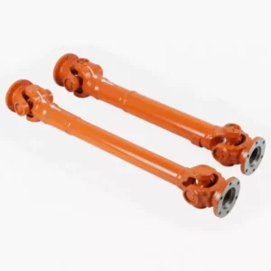
SWP-A Long Flexible Universal Joint Couplings
-
WGC Vertical Installation Drum Shape Gear Coupling
-
ML Plum Blossom Type Elastic Shaft Coupling
-
NGCLZ Drum Shape Gear Coupling with Brake Drum | Intermediate Shaft Type