Diaphragm Couplings
High-performance stainless steel diaphragm couplings for industrial power transmission — zero lubrication, torsionally rigid, operating to +280°C across a wide torque range from sub-100 N·m to over 8,000,000 N·m.
Request a QuoteAll-Metal, Zero-Lubrication Flexible Coupling
A diaphragm coupling connects two rotating shafts through one or more stainless steel diaphragm packs bolted alternately to each hub flange. As the diaphragm flexes elastically, it simultaneously transmits torque and compensates for angular, axial, and radial shaft misalignment — without any sliding contact, grease, or wear-limited element.
Compared with gear couplings, the diaphragm coupling requires no lubrication and is therefore free from the contamination, grease degradation, and re-lubrication maintenance that gear couplings demand. Compared with elastomeric couplings, its all-metal construction allows continuous service across temperature extremes from -40°C to +280°C, with torsional stiffness that does not vary with temperature or age.
GBC supplies the complete diaphragm coupling family — compact key-connection, locking device, taper sleeve, locking disc, brake disc variants, and rod-type intermediate shaft designs — covering torque from 9.8 N·m to 8,100,000 N·m. Browse the full range below, or contact our engineering team for selection support.
Diaphragm Coupling Types
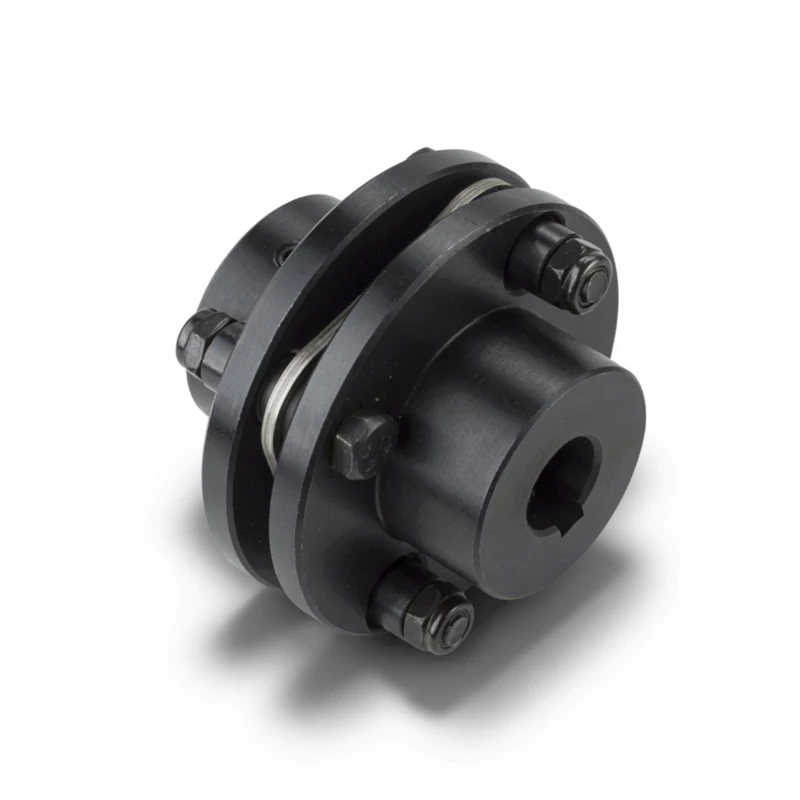 Single Pack
- Torque: 9.8–8,100,000 N·m (41 sizes)
- Speed: up to 20,000 rpm
- Hub: keyway connection
- Compact; axial and angular compensation
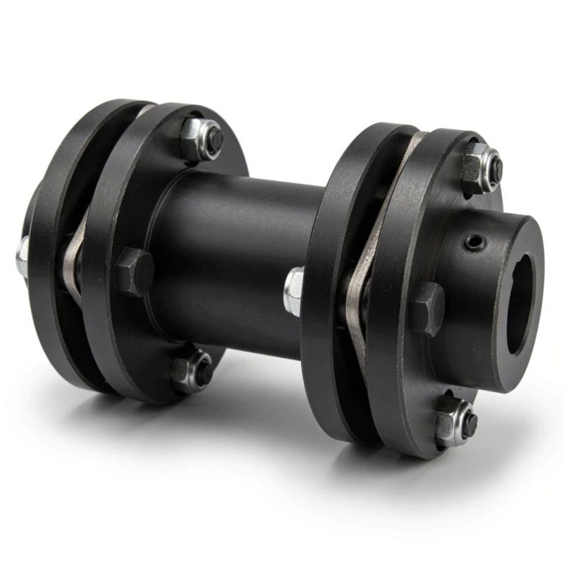 Double Pack
- Torque: 9.8–8,100,000 N·m (41 sizes)
- Radial offset: up to 3.0 mm
- Hub: keyway connection with spacer
- For turbomachinery and long shaft spans
 Zero Backlash
- Torque: 33–1,270 N·m (7 sizes)
- Speed: up to 20,000 rpm
- Hub: Z1 interference-fit locking collar
- CNC servo and ball-screw feed axes
 Low Inertia
- Torque: 33–420 N·m (5 sizes)
- Larger bore at same OD vs Z1 type
- Hub: inner/outer cone sleeve
- CNC feed shafts; minimum inertia
 Large Bore
- Torque: 33–8,100,000 N·m (40 sizes)
- Bore: up to 760 mm via Z7B disc
- Zero backlash; no keyway required
- Heavy industrial and turbomachinery
 Brake Disc
- Torque: 420–25,410 N·m (10 sizes)
- Disc OD: 315–1,000 mm
- Integrated caliper disc brake
- Servo hoists, VFD and stage drives
 Intermediate Shaft
- Torque: 40–180,000 N·m (30 sizes)
- Speed: up to 10,700 rpm
- Rod-type; single pack each end
- Back-pullout pumps; fans; long spans
 Max Compensation
- Torque: 63–180,000 N·m (29 sizes)
- Double pack each end; 2° angular
- Direct radial offset per joint
- Turbomachinery; gas turbines; large pumps
Diaphragm Types and Assembly
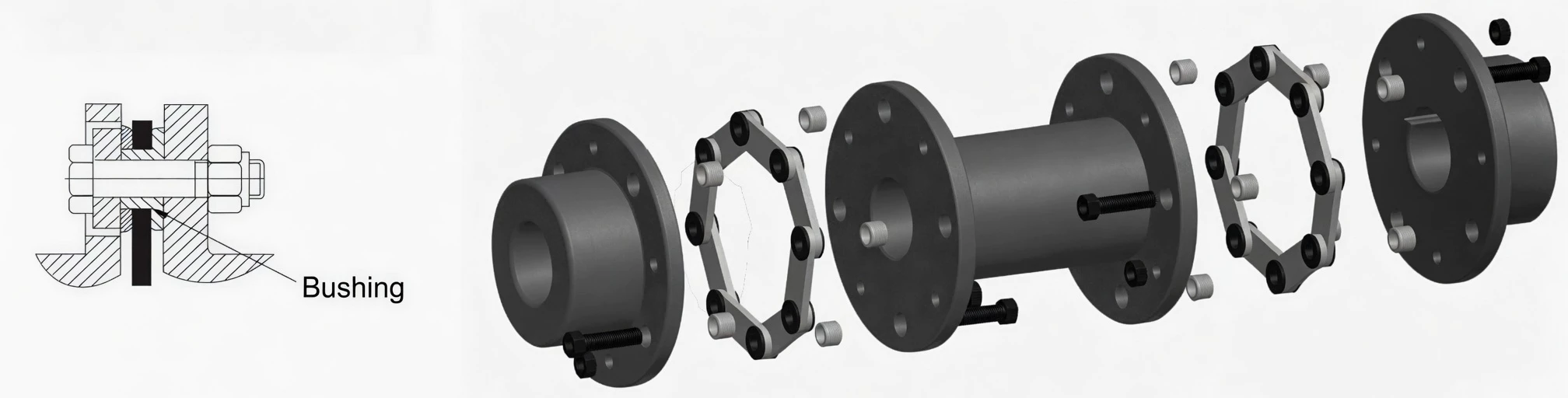
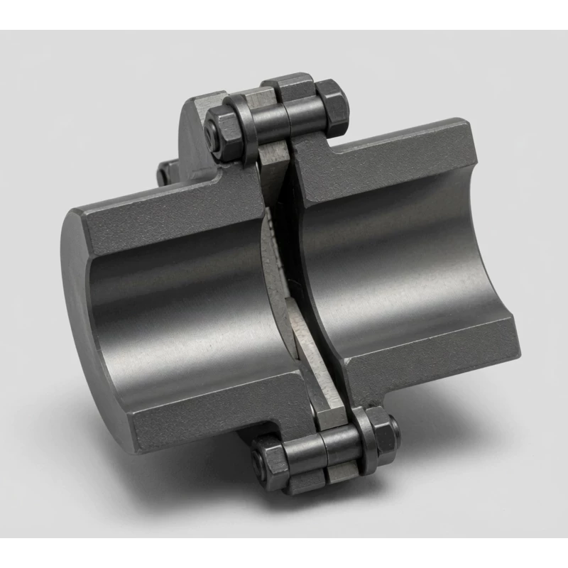
How the Diaphragm Pack Works
The diaphragm pack consists of multiple thin stainless steel sheets laminated together. Each sheet is alternately bolted to the drive flange and the driven flange in a staggered pattern: drive bolt, driven bolt, drive bolt, driven bolt, around the full bolt circle. When the drive flange rotates, tension and compression develop in alternating segments of the diaphragm, transmitting torque to the driven flange through pure elastic metal deformation.
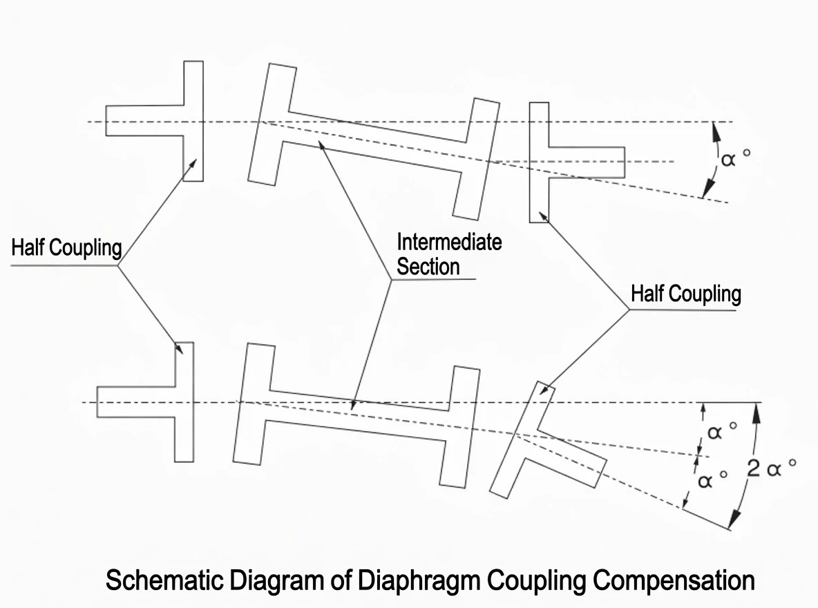
Simultaneously, the diaphragm accommodates shaft misalignment by flexing axially (bowing slightly along its centreline for axial displacement), and angularly (tilting relative to the flange face). In a double-pack coupling, two packs separated by a spacer allow the packs to flex in complementary directions, adding direct radial offset capacity without transmitting bending moments to the bearings.
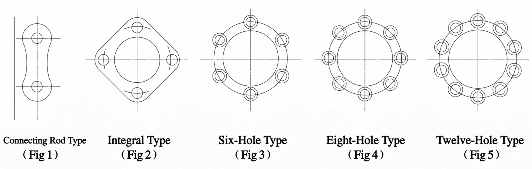
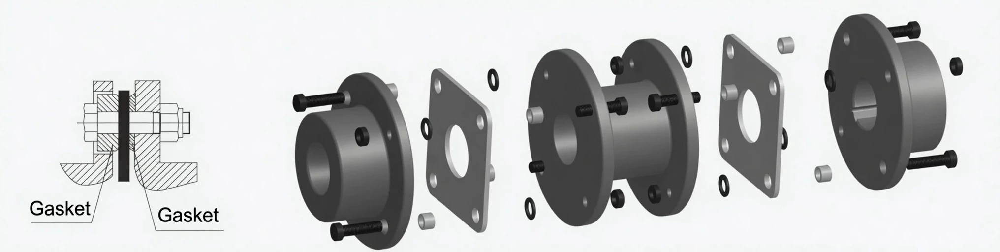
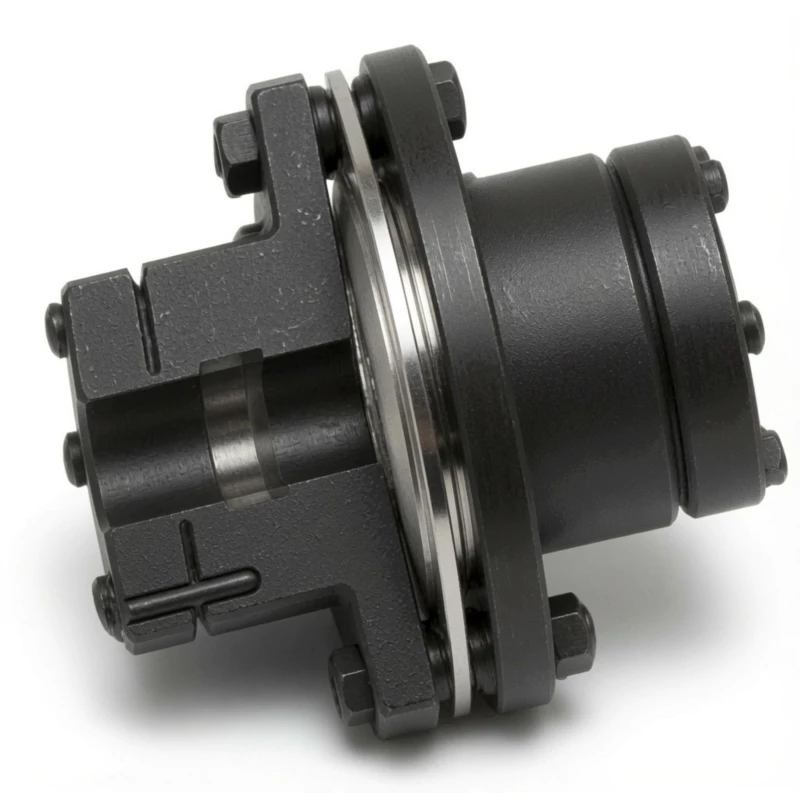
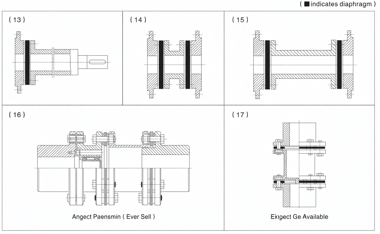
Diaphragm packs are manufactured in two main forms. The divided-link type (rod-link form, Fig.1) is used in rod-type JM/JMJ couplings and allows individual lamination replacement. The integral type (one-piece disc form, Fig.2) is used in compact DJM/SJM types and forms a single disc with 4, 6, 8, or 12 holes depending on the bolt count. Both types conform to GB/T708 diaphragm thickness standards.
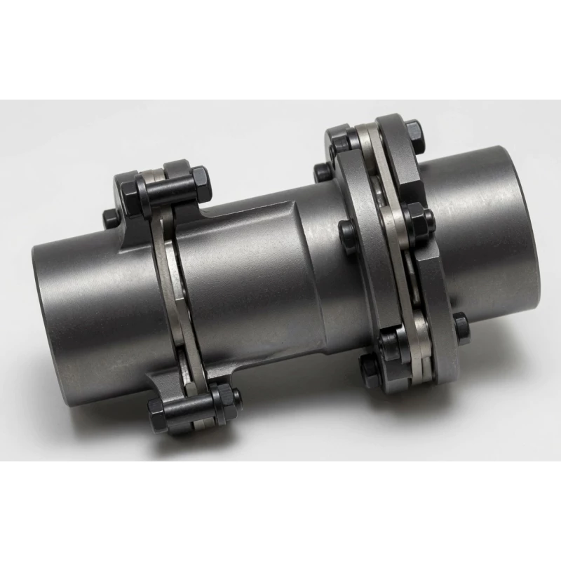
Single Pack vs Double Pack
A single-pack coupling (DJM) places one diaphragm assembly between the two hubs. It compensates axial displacement and angular misalignment at that one joint, but has limited direct radial offset capacity — radial offset is accommodated indirectly through the angular flex and produces a residual bending moment at the hub flange.
A double-pack coupling (SJM) positions two diaphragm packs on either side of a rigid spacer tube. When radial offset is present, each pack deflects angularly in opposite directions; the moments cancel at the spacer, and no net bending load reaches the shaft bearings. This makes the double pack essential for turbomachinery and drives where radial offset is unavoidable.
Shaft Hub Types Available
Standard connection. Y-type (long bore), J-type (short bore with counterbore), J1-type (short bore without counterbore). Most widely available; suitable for the majority of industrial drives.
Interference-fit cylindrical collar. Zero backlash, no keyway required. Larger bore at same OD than taper sleeve. Primarily for CNC servo axes, ball-screws, and precision positioning drives.
Inner cone (N-type) or outer cone (W-type) hub. Zero backlash, lower rotational inertia than Z1, larger bore capacity at same OD. Best choice for CNC machine tool feed shafts.
Large-diameter friction collar. Largest bore at same OD; no keyway stress concentration. Overload slip protection. For large shaft diameters above 80 mm and heavy industrial or turbomachinery applications.
Conical shaft bore (1:10 taper). Precision fit, zero clearance, repeatably removable. Suitable for smooth motor and machine shafts where precise repositioning is required.
Imperial bore sizes, non-standard bore lengths, and extended shaft lengths are available on request across all diaphragm coupling types. Specify shaft-end drawing when ordering.
How to Select a Diaphragm Coupling
Step 1 — Calculate Design Torque
Apply the service factor K to account for shock, cyclic loads, and drive type. Never select on nameplate motor torque alone.
K = service factor | P = rated power kW | N = speed rpm | Tn = nominal torque of selected size
Service Factor K Reference
| Load Character | K | Typical Applications |
|---|---|---|
| Smooth / uniform load | 1.25–1.50 | Centrifugal pumps, fans, generators |
| Moderate shock / cyclic | 1.50–2.00 | Compressors, mixers, reciprocating pumps |
| IC engine, moderate shock | 2.00–2.50 | Diesel pump sets, marine auxiliaries |
| Heavy shock / reversal | 2.50–3.00 | Crushers, hoists, rolling mill drives |
Step 2 — Choose the Right Type
| Requirement | Recommended Type |
|---|---|
| General drive, keyway shaft | DJM / SJM |
| CNC servo, ball-screw, zero backlash | DJM-Z1 or Taper Sleeve |
| Large shaft diameter, no keyway | DJM/SJM-YP Locking Disc |
| Disc brake integration | SJM-P |
| Long shaft span, back-pullout pump | JM Intermediate Shaft |
| Turbomachinery, radial offset critical | JMJ Double Intermediate Shaft |
Step 3 — Installation Error Limits
To achieve full service life, keep the installation error within the following limits. Use laser alignment for sizes above DJM-07 / SJM-07.
| Error Type | Limit | Recommended |
|---|---|---|
| Angular misalignment | Per size table (up to 2°) | ≤ 20% of allowable |
| Radial offset | Per size table | ≤ 20% of allowable |
| Axial displacement | Per size table | Within rated range |
Note: Installation error should not exceed 20% of the rated compensation value to ensure long service life. Diaphragm packs are consumable — replace immediately if cracks, fretting marks, or permanent set are observed.
Installation and Maintenance
Installation Procedure
- Cut off the power supply; clean all parts with kerosene or diesel. Tighten fixing screws and setscrew axis positioning.
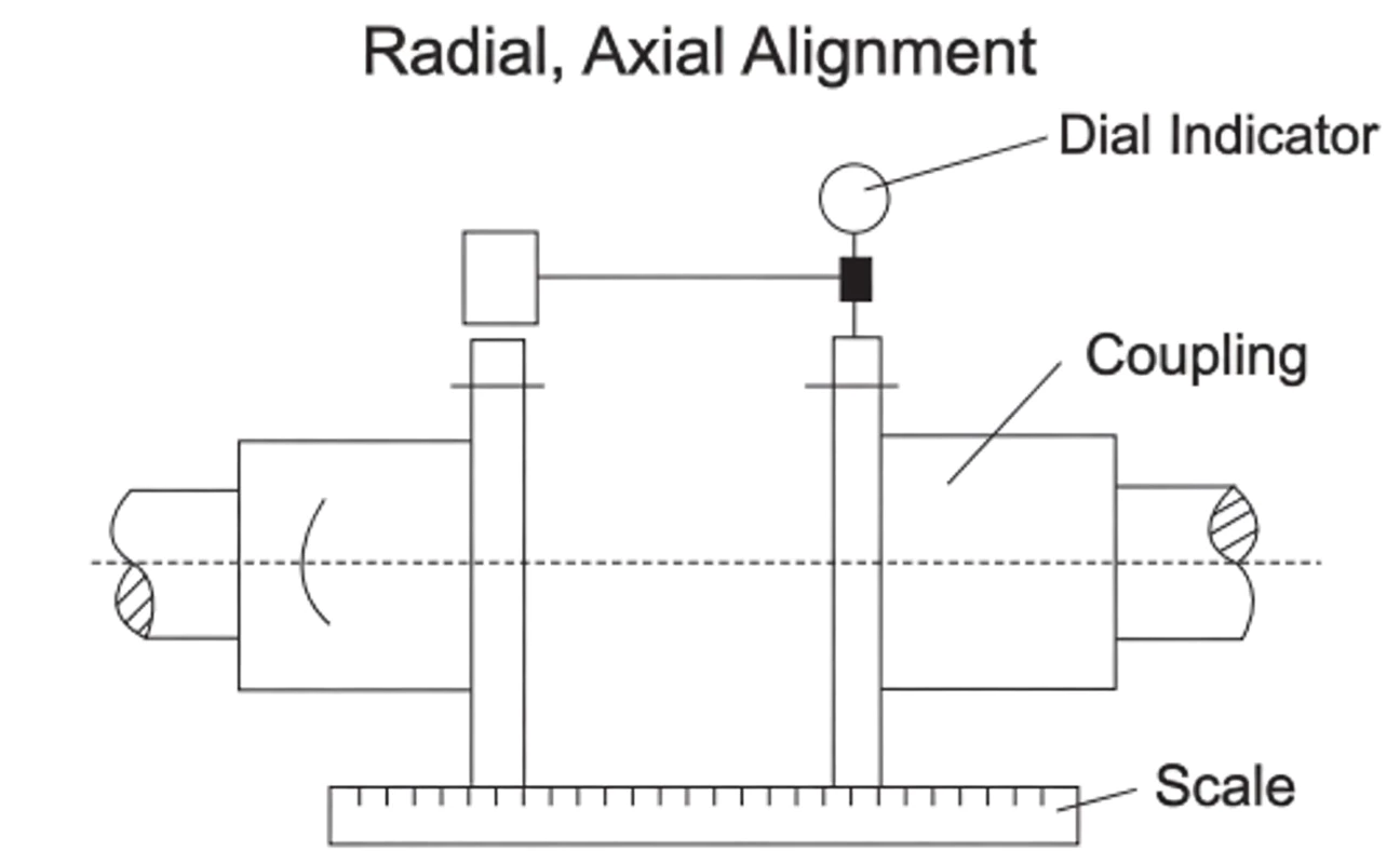
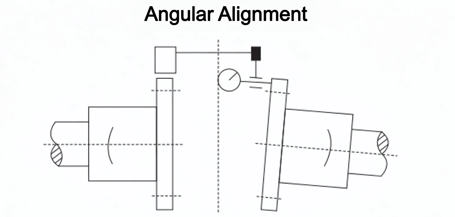
- When the machine is installed, carry out shaft alignment including axial, radial (parallel), and angular checks using dial indicators or laser alignment equipment.
- After both shafts are aligned, install the intermediate shaft and diaphragm packs, and tighten the mounting bolts in a cross-pattern in three progressive passes.
- After assembly, install a protective guard over the coupling to enhance safety.
- To improve service life, keep the installation error within 20% of the allowable compensation value.
- Replace locking nuts every time the coupling is disassembled.
Diaphragm Pack Replacement
The diaphragm pack is a consumable element. When the coupling overloads or compensates beyond its rated limits, plastic deformation or fracture of the diaphragm may result. In all such cases the diaphragm pack must be replaced as a complete group. To replace: loosen the middle coupling bolts, move the driver- or driven-side hub only after the other side is complete. Inspect all parts before fitting the new pack, and re-install to the torque values specified in the documentation.
Misalignment Types — Visual Reference
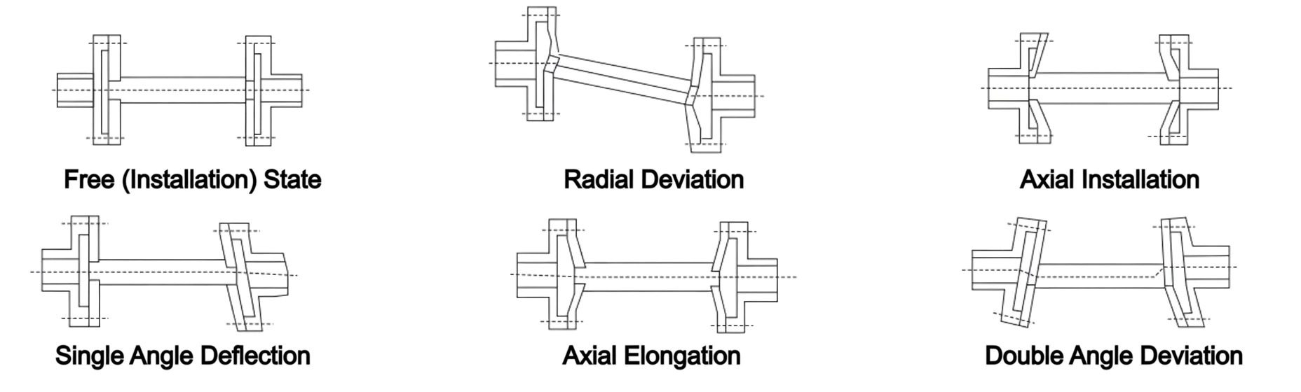
The six installation states shown above: free / installed state; radial offset; axial installation; single angular rotation; axial extension; double angular misalignment. Each condition is absorbed by the diaphragm pack's elastic bending — provided the displacement remains within the rated compensation limits for the selected coupling size.
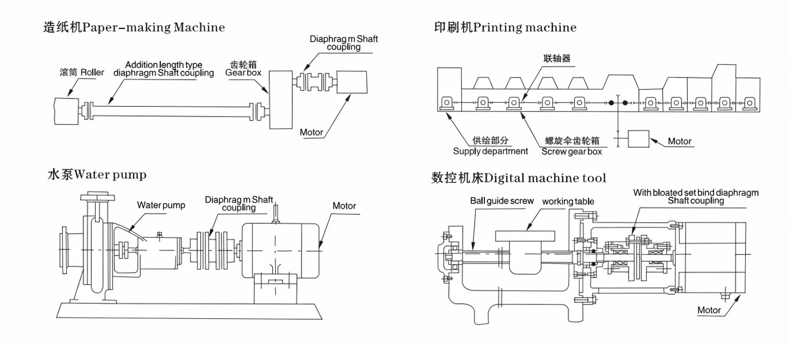
Diaphragm Coupling Applications
API 610 centrifugal pumps, back-pullout designs, high-pressure compressors. Zero lubrication critical in process environments.
Turbomachinery couplings to API 671. JMJ handles thermal growth misalignment across turbine cold-to-hot warm-up.
Servo motor to ball-screw feed axes. DJM-Z1 and taper sleeve types deliver zero-backlash, high-bandwidth servo response.
Dryer section drives, refiners, and large fans. JM intermediate shaft bridges the span; diaphragm absorbs dryer thermal growth.
Generator sets, hydro turbines, wind turbine main shafts. Zero maintenance over multi-year continuous run intervals.
Main engine to shaft line, auxiliary pump sets. All-metal construction withstands salt atmosphere and humidity.
Impression cylinder and register-critical drives. Torsional rigidity maintains print registration under load changes.
Rolling mill auxiliaries, large fans, and crusher drives. Locking disc YP types handle large shaft diameters without keyway stress.
Diaphragm Coupling FAQ
Need Help Selecting a Diaphragm Coupling?
Send us your motor power, speed, shaft diameters, operating temperature, and shaft-end gap — our engineering team will recommend the correct type and size within 24 hours and confirm dimensional compatibility.