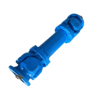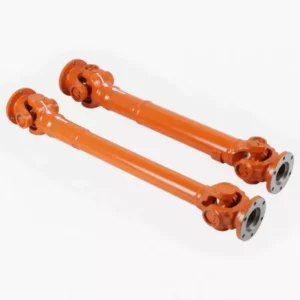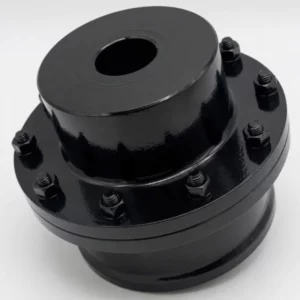
JMJ Type Double Diaphragm Coupling with Intermediate Shaft
The JMJ Type Double Diaphragm Coupling with Intermediate Shaft (rod type) fits two double-pack diaphragm assemblies — one at each end of a rigid spacer tube — to deliver the maximum misalignment capacity available in the diaphragm coupling family. Spanning 29 sizes from JMJ1 (63 N·m) to JMJ29 (180,000 N·m) at speeds up to 9,300 rpm, it handles simultaneous angular, axial, and radial shaft offset across long spans where both alignment precision and access for maintenance are challenging.
What Is a JMJ Type Double Diaphragm Coupling with Intermediate Shaft?
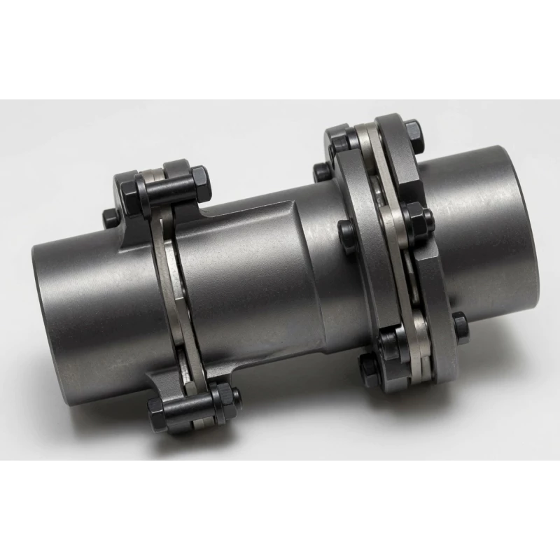
The JMJ type double diaphragm coupling with intermediate shaft represents the maximum misalignment capacity available in the diaphragm coupling family. Where the JM single-pack rod type provides angular and axial compensation at each shaft end, the JMJ doubles this by fitting a double pack (two diaphragm assemblies) at each end of the intermediate shaft — identical in principle to the compact SJM double-pack coupling, but deployed at both ends of a spacer tube to span large shaft-to-shaft gaps.
The practical result is a coupling that simultaneously tolerates angular misalignment (up to 2° per end), axial displacement, and direct radial offset at each joint — the only rod-type diaphragm coupling that provides true three-dimensional misalignment accommodation across long shaft spans. This makes the JMJ the standard selection for large turbomachinery trains, heavy-duty centrifugal pump installations, and paper machine drives where the combined effects of thermal growth, foundation settlement, and installation tolerance produce misalignment in all three axes simultaneously.
Why Double Pack at Each End Matters
In a single-pack rod type (JM), radial shaft offset produces a bending moment at the single-pack joint that is transmitted to the shaft bearing as a side load. A double pack at each end creates a two-pack cantilever: radial offset causes the outer and inner pack to deflect in complementary directions, cancelling the net moment at the hub flange. The result is that radial offset generates near-zero bearing side load — a critical property for large turbomachinery bearings that are sensitive to even small additional loads.
JMJ vs JM — Comprehensive Comparison
| Feature | JMJ Double Pack | JM Single Pack |
|---|---|---|
| Packs per end | 2 | 1 |
| Angular compensation per end | 2° | 1° |
| Radial offset capacity | Direct per joint | Indirect (via angular) |
| Bearing side load from radial offset | Near zero | Present |
| Hub OD (D1) at same torque | Larger | Smaller |
| Mass | Higher | Lower |
| Best for | Multi-axis misalignment, thermal offset, turbomachinery | Well-aligned long spans, back-pullout pumps |
JMJ Coupling Specifications and Dimensions
Materials
Diaphragm packs (four total — two at each end): stainless steel sheet. Hubs: alloy steel. Intermediate shaft tube: precision alloy steel tube. Torsional stiffness and inertia values are calculated at minimum recommended L1. Custom shaft lengths, imperial bore, and corrosion-resistant coatings available.
Ordering Mark Example
→ JMJ size 12 | Y-bore A-keyway drive d=75 mm L=142 mm | Y-bore A-keyway driven d=85 mm L=172 mm | spacer L1=190 mm
Complete Parameter Table — JMJ1 to JMJ29
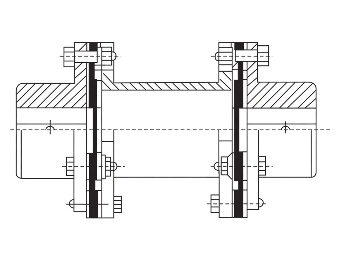
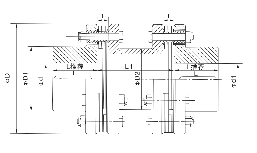
D = flange OD (mm). D1 = outer hub OD (mm). D2 = inner hub OD (mm). L1 = minimum recommended intermediate shaft length (mm). t = diaphragm pack thickness (mm). Mass is minimum L1 value; increments per 1 m additional length as listed. Angular comp: 2° per end. "—" = not listed for this size.
| Type | Nom. Torque N·m | Inst. Torque N·m | Max Speed rpm | Bore d mm | L rec. mm | D mm | D1 mm | D2 mm | L1 mm | t mm | Mass kg | +1m kg | Inertia Kg·m² |
|---|---|---|---|---|---|---|---|---|---|---|---|---|---|
| JMJ1 | 63 | 100 | 9,300 | 20,22,24 / 25,28 / 30,32,35,38 | 40 | 92 | 53 | 45 | 70 | 8±0.2 | 2 | 4.1 | 0.002 |
| JMJ2 | 100 | 200 | 8,400 | 25,28 / 30,32,35,38 / 40,42,45 | 45 | 102 | 63 | 45 | 80 | 8±0.2 | 2.9 | 4.1 | 0.003 |
| JMJ3 | 250 | 400 | 6,700 | 30,32,35,38 / 40,42,45,48,50,55 | 55 | 128 | 77 | 45 | 96 | 11±0.3 | 5.7 | 8 | 0.009 |
| JMJ4 | 500 | 800 | 5,900 | 35,38 / 40,42,45,48,50,55,56 / 60,63,65 | 65 | 145 | 91 | 45 | 116 | 11±0.3 | 8.5 | 8 | 0.017 |
| JMJ5 | 800 | 1,250 | 5,100 | 40,42,45,48,50,55,56 / 60,63,65,70,71,75 | 75 | 168 | 105 | 45 | 136 | 14±0.3 | 12.5 | 12 | 0.034 |
| JMJ6 | 1,250 | 2,000 | 4,750 | 45,48,50,55,56 / 60,63,65,70,71,75 / 80 | 80 | 180 | 112 | 102 | 140 | 15±0.4 | 16.5 | 12 | 0.053 |
| JMJ7 | 2,000 | 3,150 | 4,300 | 50,55,56 / 60,63,65,70,71,75 / 80,85 | 80 | 200 | 120 | 114 | 140 | 15±0.4 | 21 | 19 | 0.082 |
| JMJ8 | 2,500 | 4,000 | 4,200 | 55,56 / 60,63,65,70,71,75 / 80,85 | 80 | 205 | 120 | 114 | 140 | 20±0.4 | 23 | 19 | 0.092 |
| JMJ9 | 3,150 | 5,000 | 4,000 | 55,56 / 60,63,65,70,71,75 / 80,85,90 | 90 | 215 | 128 | 127 | 160 | 20±0.4 | 27 | 21 | 0.117 |
| JMJ10 | 4,000 | 6,300 | 3,650 | 60,63,65,70,71,75 / 80,85,90,95 | 100 | 235 | 132 | 127 | 170 | — | 36 | 21 | 0.191 |
| JMJ11 | 5,000 | 8,000 | 3,400 | 60,63,65,70,71,75 / 80,85,90,95 / 100 | 100 | 250 | 145 | 140 | 170 | 23±0.5 | 42 | 26 | 0.252 |
| JMJ12 | 6,300 | 10,000 | 3,200 | 60,63,65,70,71,75 / 80,85,90,95 / 100,110 | 110 | 270 | 155 | 140 | 190 | — | 50 | 26 | 0.349 |
| JMJ13 | 8,000 | 12,500 | 2,850 | 65,70,71,75 / 80,85,90,95 / 100,110 | 115 | 300 | 162 | 140 | 200 | 27±0.6 | 66 | 47 | 0.56 |
| JMJ14 | 10,000 | 16,000 | 2,700 | 70,71,75 / 80,85,90,95 / 100,110,120,125 | 125 | 320 | 176 | 165 | 220 | 27±0.6 | 78 | 47 | 0.75 |
| JMJ15 | 12,500 | 20,000 | 2,450 | 75 / 80,85,90,95 / 100,110,120,125 / 130 | 140 | 350 | 186 | 165 | 240 | — | 110 | 51 | 1.26 |
| JMJ16 | 16,000 | 25,000 | 2,300 | 80,85,90,95 / 100,110,120,125 / 130,140 | 145 | 370 | 203 | 165 | 250 | 32±0.7 | 125 | — | 1.63 |
| JMJ17 | 20,000 | 31,500 | 2,150 | 90,95 / 100,110,120,125 / 130,140,150 / 160 | 165 | 400 | 230 | 219 | 290 | — | 160 | 72 | 2.45 |
| JMJ18 | 25,000 | 40,000 | 1,950 | 100,110,120,125 / 130,140,150 / 160,170 | 175 | 440 | 245 | 219 | 300 | 38±0.9 | 220 | — | 3.99 |
| JMJ19 | 31,500 | 50,000 | 1,850 | 100,110,120,125 / 130,140,150 / 160,170,180 | 185 | 460 | 260 | 219 | 320 | — | 245 | — | 4.98 |
| JMJ20 | 35,500 | 56,000 | 1,800 | 120,125 / 130,140,150 / 160,170,180 / 190,200 | 200 | 480 | 280 | 267 | 350 | 38±0.9 | 275 | 89 | 6.28 |
| JMJ21 | 40,000 | 63,000 | 1,700 | 120,125 / 130,140,150 / 160,170,180 / 190,200 | 210 | 500 | 295 | 267 | 370 | — | 320 | — | 7.68 |
| JMJ22 | 50,000 | 80,000 | 1,600 | 140,150 / 160,170,180 / 190,200,220 | 220 | 540 | 310 | 299 | 380 | 44±1 | 400 | 110 | 11.6 |
| JMJ23 | 63,000 | 100,000 | 1,450 | 140,150 / 160,170,180 / 190,200,220 / 240 | 240 | 600 | 335 | 299 | 410 | — | 560 | — | 19.8 |
| JMJ24 | 80,000 | 125,000 | 1,400 | 160,170,180 / 190,200,220 / 240,250 | 255 | 620 | 350 | 356 | 440 | 50±0.1 | 620 | 145 | 23.6 |
| JMJ25 | 90,000 | 140,000 | 1,300 | 180 / 190,200,220 / 240,250,260 / 280 | 275 | 660 | 385 | 356 | 480 | — | 740 | — | 31.9 |
| JMJ26 | 112,000 | 180,000 | 1,200 | 180 / 190,200,220 / 240,250,260 / 280,300 | 295 | 720 | 410 | 406 | 510 | — | 970 | 190 | 50.4 |
| JMJ27 | 140,000 | 200,000 | 1,150 | 220 / 240,250,260 / 280,300 | 300 | 740 | 420 | 406 | 520 | 60±1.4 | 1050 | — | 57 |
| JMJ28 | 160,000 | 224,000 | 1,100 | 240,250,260 / 280,300 / 320 | 320 | 770 | 450 | 457 | 560 | — | 1200 | — | 69.4 |
| JMJ29 | 180,000 | 280,000 | 1,050 | 250,260 / 280,300,320 / 340 | 350 | 820 | 490 | 457 | 600 | — | 1400 | 215 | 95.5 |
Note: Mass and inertia calculated at minimum L1. +1m = additional mass per 1 m increase in shaft length. Angular compensation: 2° per joint (both ends). "—" = not tabulated for this size; contact GBC engineering for confirmation.
How to Select a JMJ Coupling
Design Torque Calculation
When to Choose JMJ over JM
- Radial shaft offset is a primary design constraint (turbomachinery thermal growth, soft-foot, foundation creep)
- Both angular and radial misalignment are present simultaneously at the same shaft end
- Bearing side load from misalignment must be minimised — critical for large hydrodynamic bearings
- The drive involves high-speed precision shafts where any shaft deflection from misalignment causes vibration
- Shaft-end gaps are large (1–5 m) and the intermediate shaft cannot practically be supported by a steady bearing
Intermediate Shaft Length and Critical Speed
L1 in the table is the minimum recommended intermediate shaft length. Custom L1 can be specified for any required shaft gap. For L1 above 1.5 m, GBC engineering performs a lateral critical speed calculation; operating speed must not exceed 75% of the first lateral critical speed of the unsupported intermediate shaft to avoid resonant whip.
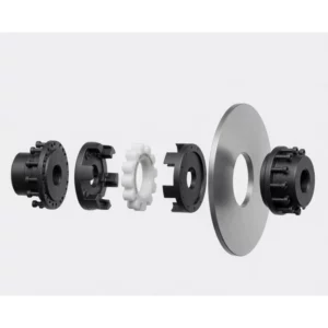
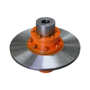
Related Diaphragm Coupling Types
9.8–8,100,000 N·m · No intermediate shaft · Close-coupled drives
420–25,410 N·m · Integrated disc brake · Compact
40–180,000 N·m · Single pack each end · 1° angular · Long spans
63–180,000 N·m · Double pack each end · 2° angular · Radial offset · Max misalignment
For long-span drives where angular compensation is sufficient and radial offset is minimal, the JM single-pack type provides a lighter, lower-cost alternative with a smaller hub OD.
Applications
API 671 turbomachinery couplings for gas turbine to centrifugal compressor trains. The JMJ accommodates the full cold-to-hot misalignment envelope — thermal growth of turbine and compressor in all three axes — while transmitting torque with the torsional stiffness required for accurate rotor dynamic analysis. The zero-lubrication diaphragm packs provide the maintenance-free operation mandated on remote or offshore installations.
High-pressure boiler feed pump turbine (BFPT) to pump couplings involve large shaft-to-shaft gaps and significant thermal misalignment during load changes. JMJ-22 through JMJ-26 cover the typical torque range for these trains; the double-pack radial compensation prevents bearing overloading during the large thermal transients of a cold start.
Large hydro turbine shaft to generator coupling, shaft spans 800 mm to 2,000 mm. JMJ handles the combined angular misalignment from guide bearing clearances and radial offset from runner hydraulic loads. Zero lubrication is essential in hydro installations where any oil contamination would affect penstock and turbine components.
Vertical inline pump configurations often have the motor mounted directly above the pump with a long shaft span. The combined effect of motor bearing clearances, pump hydraulic radial loads, and foundation settling produces simultaneous angular and radial misalignment that the JMJ double-pack handles without transmitting side loads to the pump mechanical seal.
Large two-stroke or four-stroke main engine to intermediate shaft line couplings on bulk carriers, tankers, and container ships. JMJ spans the gap between engine crankshaft and shaft line at the engine room bulkhead, absorbing hull flexing misalignment (angular and radial) while transmitting full main engine torque.
Heavy-duty screw compressor and large reciprocating compressor input shaft couplings use JMJ for the combination of high torque, shock load absorption at the double-pack (twice the damping nodes vs JM), and radial compensation for the thermal growth typical of continuously-operating compressor packages in petrochemical service.
Installation and Maintenance
- Hub fitting: Press or heat both sets of hub pairs onto their shafts. At each end, the inner and outer hub components of the double-pack assembly must be fitted in the correct sequence — follow the assembly drawing supplied with the coupling.
- Shaft alignment: Align both shaft ends with laser equipment. The JMJ tolerates larger misalignment than JM but maximising alignment at installation maximises diaphragm service life.
- Intermediate shaft insertion: Insert the intermediate shaft tube between the two end assemblies. Confirm the tube length provides the correct end gap at both joints with diaphragm packs in their neutral (unloaded) position.
- Diaphragm packs — both ends: Fit all four diaphragm packs (two per end). Torque all bolts to specification in three cross-pattern passes. Verify bolt torque at both ends — mismatched torque produces unequal pack stress and uneven misalignment tolerance.
- Critical speed verification: For L1 above 1 m, calculate lateral critical speed before commissioning. Operating speed must not exceed 75% of the first lateral mode frequency.
| Symptom | Likely Cause | Action |
|---|---|---|
| High 1× or 2× vibration | Misalignment at one or both ends; imbalance | Re-align; balance intermediate shaft |
| Intermediate shaft whip | Operating near lateral critical speed | Reduce speed; add intermediate support bearing |
| Diaphragm crack at one end | Misalignment at that joint exceeds 2°; overload | Replace packs; re-align that end; check TC |
| Bolt fretting at pack | Under-torqued pack bolts | Replace pack; re-torque to specification |
Customer Case Studies
Australia — Offshore Gas Platform, Compressor Train
JMJ-18 on a gas turbine to centrifugal compressor coupling aboard a floating production platform. The coupling must handle combined roll-induced angular misalignment of the platform hull and thermal growth of the turbine — simultaneously. The double-pack design absorbs both without transmitting side loads to the compressor journal bearings. Eighteen months of continuous offshore operation without any coupling-related maintenance.
Rotating Machinery Specialist, Western Australia AU
★★★★★
Japan — Large Hydroelectric Station
JMJ-24 and JMJ-25 on the main turbine-generator shaft coupling at a 400 MW hydroelectric station. The 1,200 mm intermediate shaft spans the distance between turbine runner hub and generator lower journal bearing. The double-pack radial compensation absorbs runner hydraulic radial thrust that would otherwise load the generator bearing. Zero maintenance in four years of continuous generation.
Mechanical Engineering Manager, Hokkaido JP
★★★★★
Netherlands — LNG Terminal, Booster Compressor
JMJ-20 coupling on a high-pressure booster compressor driver train. The double-pack design was specified by the EPC contractor to meet API 671 lateral stiffness requirements. Dimensional accuracy on delivery matched the coupling drawing within 0.1 mm. The package has been in continuous service for 26 months without inspection — meeting the planned 3-year overhaul interval.
Reliability Engineer, Rotterdam NL
★★★★☆
Brazil — Steel Mill, ID Fan Drive
JMJ-16 and JMJ-17 on two large induced-draft fan drives at a blast furnace facility. The combination of high shaft-to-shaft gap (850 mm), fan hydraulic radial loading, and foundation settlement from ground vibration makes the double-pack JMJ essential — JM single-pack couplings on an earlier installation caused chronic bearing failures due to transmitted misalignment side loads.
Maintenance Engineering Supervisor, Rio de Janeiro BR
★★★★★
Frequently Asked Questions
▶ What is the key advantage of JMJ over JM for turbomachinery?
The double pack at each end of the JMJ allows direct radial shaft offset without transmitting bending moments to the machine bearings. In turbomachinery, bearing side load from coupling misalignment is a primary cause of bearing wear and reduced L10 life. A single-pack JM joint transmits a bending moment proportional to the radial offset; the double-pack JMJ joint cancels this moment by equal and opposite deflection of its two packs. For large hydrodynamic bearings where even 5–10% additional load shortens bearing life significantly, this distinction is decisive.
▶ Can a JMJ coupling handle thermal growth misalignment during warm-up?
Yes — this is the central use case. During warm-up from cold to operating temperature, turbomachinery casing thermal growth produces simultaneous axial displacement, angular rotation, and radial shaft offset at the coupling as the relative positions of motor, gearbox, and driven machine change. The JMJ accommodates all three simultaneously at each end. The intermediate shaft floats axially between the two end assemblies, so axial growth of either machine is absorbed without pre-loading the packs.
▶ What does L1 represent in the JMJ parameter table?
L1 is the minimum recommended intermediate shaft length for each size. Custom shaft lengths can be specified for any required shaft-end gap. The tabulated mass value is for the minimum L1; the '+1m' column shows the additional mass per 1 m increase in shaft length for weight estimation. For shaft lengths above 1.5 m, a lateral critical speed calculation is required — the operating speed must not exceed 75% of the first lateral critical speed of the unsupported intermediate shaft.
▶ How are the four diaphragm packs of a JMJ coupling maintained?
The four diaphragm packs (two at each end) require no lubrication and no routine maintenance under normal conditions. Inspect all four packs visually at each major shutdown — typically annually or at the specified overhaul interval. Replace any pack showing cracks, bolt-hole fretting, or material thinning. Pack replacement does not require hub removal from the shaft — only the pack mounting bolts are undone at each end. Use the same calibrated torque and cross-pattern tightening sequence at both ends when refitting.
▶ Can a JMJ coupling replace a gear coupling on an existing turbomachinery train?
In most cases yes, subject to dimensional compatibility. JMJ provides comparable torque capacity to an equivalent gear coupling but without lubrication requirements, with zero-backlash performance, and with higher torsional stiffness. The hub OD (D1) of the JMJ double-pack is larger than a compact SJM at the same torque, but typically compatible with the existing shaft arrangement. Supply GBC with the existing coupling dimensional drawing, shaft diameters, torque, speed, and shaft-end gap and the engineering team will confirm JMJ compatibility and provide a proposal.
Source JMJ Intermediate Shaft Couplings for Your Drive Train
GBC supplies all 29 JMJ sizes with custom intermediate shaft lengths, rotordynamic critical speed analysis for long shafts, API 671 balance certification, and full dimensional documentation. Send your motor power, speed, shaft-end gap, shaft diameters, and misalignment envelope and our engineering team will confirm the correct JMJ size and shaft length within 24 hours.
The JMJ Type Double Diaphragm Coupling with Intermediate Shaft (rod type) fits two double-pack diaphragm assemblies — one at each end of a rigid spacer tube — to deliver the maximum misalignment capacity available in the diaphragm coupling family. Spanning 29 sizes from JMJ1 (63 N·m) to JMJ29 (180,000 N·m) at speeds up to 9,300 rpm, it handles simultaneous angular, axial, and radial shaft offset across long spans where both alignment precision and access for maintenance are challenging.