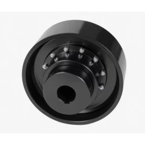
MLP Type Plum Blossom Coupling with Brake Disc
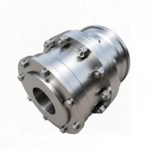
The MLP Type Plum Blossom Coupling with Brake Disc integrates a disc-brake rotor directly with the jaw coupling assembly, enabling caliper-type disc braking in a single compact unit. Available in nine sizes — MLP6 through MLP14 — covering nominal torque 630–12,500 N·m and braking torque up to 40,050 N·m, with brake disc diameters 355–1,000 mm and a split outer hub that allows the polyurethane spider to be replaced without moving either machine shaft.
What Is an MLP Plum Blossom Coupling with Brake Disc?
The MLP plum blossom coupling with brake disc is the disc-brake member of the GB/T5272-2002 jaw coupling family. Where LMZ-I and LMZ-II integrate drum (shoe) brakes, the MLP integrates a flat disc rotor — the working surface for a caliper-type disc brake. This design delivers smoother, more consistent braking torque, superior heat dissipation, and easier brake lining inspection compared to drum equivalents. It is the preferred choice for variable-frequency drives, precision hoists, and any application where braking repeatability and minimal thermal runaway risk are critical.
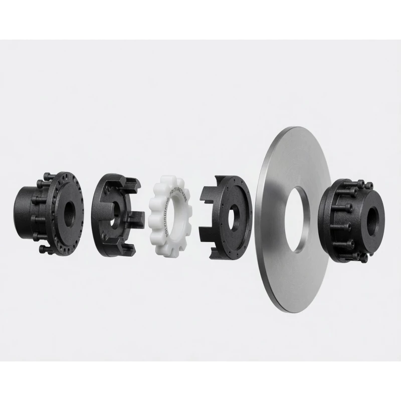
MLP Assembly Architecture
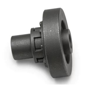
- Inner hub (fixed to shaft) — carries the claw profile; cast iron. Keyed and setscrew-retained.
- Outer hub section (split, removable) — bolts to the inner hub OD. Removed radially to access the spider without shaft movement.
- Brake disc — flat annular rotor bolted to the outer hub section. Available diameters 355–1,000 mm; interchangeable without hub removal.
- Driven hub — standard LM-type hub on the opposing shaft.
- Polyurethane spider — shA or shD grade; replaced by removing the outer hub section radially, with no shaft movement required.
Disc Brake vs Drum Brake — Why MLP?
| Feature | MLP (Disc Brake) | LMZ-I / LMZ-II (Drum Brake) |
|---|---|---|
| Braking consistency | ★★★★★ Excellent | ★★★★☆ Good |
| Heat dissipation | Superior (open disc) | Moderate (enclosed drum) |
| Lining inspection | Visual, no disassembly | Cover removal needed |
| Brake fade at high duty | Lower risk | Higher risk at high cycle rate |
| Max coupling torque (standard) | 12,500 N·m | Up to 25,000 N·m (LMZ-I) |
| Suitable for VFD drives | ✓ Yes — precise control | ✓ Yes, but less precise |
MLP Coupling Specifications & Dimensions
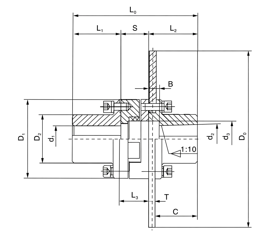
Hub: cast iron · Spider: polyurethane −35 °C to +80 °C · L0 = total length · S = hub gap · L3 = hub length · C = disc centre distance (mm) · D0×T = disc outer diameter × thickness · * = bore compatible with Z/J hole types
| Type | Old | Nom. Torque N·m |
Braking Torque N·m |
Max Speed rpm |
Bore & Length | S mm | L3 mm | D1 mm | D2 mm | B mm | D3 mm | R mm | C mm | D0×T mm | ||
|---|---|---|---|---|---|---|---|---|---|---|---|---|---|---|---|---|
| d1,d2 mm | L1,L2 (Y/Z) | L0 mm | ||||||||||||||
| MLP6 | MLPK6 | 630 | 1,800 | 3,500 | 35, 38 | 82 | 231 | 67 | 71 | 145 | 85 | 22 | 65 | 2 | 70 | 355×20 |
| 40, 42 | 82 | 231 | 100 | 400×20 | ||||||||||||
| 45, 48, 50, 55 | 112 | 291 | 95 | 450×30 | ||||||||||||
| MLP7 | MLPK7 | 1,120 | 2,850 | 3,250 | 45, 48 | 112 | 291 | 67 | 71 | 170 | 110 | 28 | 80 | 2 | 95 | 400×30 |
| 50, 55 | 112 | 291 | 95 | 450×30 | ||||||||||||
| 60, 63, 65 | 142 | 351 | 125 | 500×30 | ||||||||||||
| MLP8 | MLPK8 | 1,800 | 4,950 | 3,000 | 50, 55 | 112 | 300 | 76 | 81 | 200 | 135 | 28 | 95 | 2.5 | 94 | 450×30 |
| 60, 63 | 142 | 360 | — | 400×30 | ||||||||||||
| 65, 70 | 142 | 360 | 124 | 500×30 | ||||||||||||
| 71, 75 | 142 | 360 | — | 560×30 | ||||||||||||
| MLP10 | MLPK9 | 2,800 | 7,740 | 2,800 | 60, 63 | 142 | 364 | 80 | 86 | 230 | 160 | 35 | 116 | 2.5 | 124 | 500×30 |
| 65, 70, 71, 75 | 142 | 364 | 124 | 560×30 | ||||||||||||
| 80, 85, 90, 95 | 172 | 424 | 154 | 630×30 | ||||||||||||
| MLP11 | MLPK10 | 4,500 | 11,940 | 2,600 | 70, 71, 75 | 142 | 379 | 95 | 101 | 262 | 180 | 40 | 140 | 2.5 | 124 | 500×30 |
| 80, 85 | 172 | 439 | 154 | 560×30 | ||||||||||||
| 90, 95 | 172 | 439 | 154 | 630×30 | ||||||||||||
| 100, 110 | 212 | 519 | 194 | 710×30 | ||||||||||||
| MLP12 | MLPK11 | 7,100 | 17,550 | 2,250 | 80, 85 | 172 | 455 | 111 | 117 | 300 | 200 | 40 | 150 | 3 | 154 | 630×30 |
| 90, 95 | 172 | 455 | 154 | 710×30 | ||||||||||||
| 100, 110, 120 | 212 | 535 | 194 | 800×30 | ||||||||||||
| MLP13 | MLPK12 | 11,200 | 29,100 | 2,000 | 90, 95 | 172 | 469 | 124 | 130 | 360 | 225 | 45 | 210 | 3 | 154 | 710×30 |
| 100, 110, 120, 125 | 212 | 548 | 194 | 800×30 | ||||||||||||
| 100, 110, 120, 125 | 212 | 548 | 194 | 900×30 | ||||||||||||
| 130 | 252 | 628 | 234 | 900×30 | ||||||||||||
| MLP14 | MLPK13 | 12,500 | 40,050 | 1,800 | 100, 110, 120, 125 | 212 | 548 | 124 | 130 | 400 | 240 | 50 | 235 | 3 | 194 | 900×30 |
| 130, 140, 150 | 252 | 628 | 234 | 1000×30 | ||||||||||||
Related Plum Blossom Coupling Types
GBC manufactures the complete plum blossom coupling range. Browse the full jaw coupling catalogue for dimensional drawings and cross-reference tables.
Torque: 16–8,000 N·m · No brake · General industrial drives
Torque: 25–25,000 N·m · No brake · Radial spider replacement
Torque: 250–25,000 N·m · Drum brake · Split wheel, in-situ replacement
Torque: 250–12,500 N·m · Drum brake · Compact integral drum
Torque: 630–12,500 N·m · Disc brake · Spider replaceable in situ
How to Select an MLP Coupling
Step 1 — Coupling Design Torque
Apply service factor K (1.25–3.0), motor power P in kW, and speed N in rpm. Select the MLP size whose nominal torque Tn ≥ TC.
Step 2 — Brake Disc Selection
Select D0×T matching your caliper geometry and braking torque demand. The centre distance C positions the disc face relative to the caliper mounting bracket. Each size offers multiple disc options — see the parameter table above. Verify radial clearance: the disc OD protrudes beyond D1.
Ordering Mark Format
→ MLP type, size 10 · Disc D0=500 mm, T=30 mm, C=124 mm
→ Drive: Y-bore A-keyway 80×172 · Driven: Z-bore C-keyway 60×142
Key Selection Considerations
- Braking torque check: The disc brake braking torque must not exceed the coupling's nominal torque Tn. Confirm caliper force × effective disc radius ≤ Tn.
- Disc clearance: Verify radial and axial clearance against the drive housing and caliper bracket before finalising the disc option.
- Spider grade: shA (general purpose) for smooth VFD deceleration; shD (soft, high-damping) for drives with abrupt stop-start or heavy shock loads.
- Speed limit: Larger disc sizes add rotating mass — always verify operating speed is below the rated maximum for the selected size and disc combination.
Industry Applications
⚡ VFD-Driven Hoists & Winches
Disc brakes are the natural partner for variable-frequency drives because caliper force is electronically adjustable, enabling smooth ramp-down braking. MLP couplings on VFD hoist drives deliver precise load-lowering speed control without brake fade common with drum brakes at high cycle rates.
Automated Warehousing & AS/RS
Stacker cranes and automated storage retrieval systems demand high-cycle, precise braking on X/Y travel and lift drives. MLP's disc brake provides consistent stopping position accuracy cycle after cycle — critical for pallet rack alignment.
Stage & Entertainment Rigging
Counterweight fly-tower drives and motorised scenic automation use MLP for its disc brake's quiet operation and precise holding torque. The vibration-damping spider protects sensitive theatrical drive trains from motor start-stop shock.
️ Wind Turbine Ancillary Drives
Yaw and pitch system auxiliary drives use MLP for its compact size, disc brake precision, and polyurethane spider's tolerance of vibration and shock loads inherent in turbine operation.
️ Crane Auxiliary Drives
Jib rotation and slewing drives on cranes use MLP for its precise disc braking. The visual lining inspection advantage is valuable at crane service heights where drum cover removal presents a safety hazard.
Pharmaceutical & Cleanroom
Cleanroom-compatible coating drum drives and sterile filling line conveyors benefit from MLP's open disc face, which allows pad inspection during cleaning rounds without disassembly — supporting GMP audit requirements.
For heavier drives requiring drum-brake integration, see our LMZ-I split brake wheel and LMZ-II integral brake wheel coupling pages.
Installation & Maintenance
Installation Steps
- Press inner hubs onto both shafts; torque all setscrews. Use induction heater (≤120 °C) for interference fits.
- Align shafts within coupling angular (≤2°) and radial tolerances; laser alignment recommended.
- Insert the polyurethane spider between the inner hub claw faces.
- Fit the outer hub section radially and bolt to the inner hub body; torque bolts in a cross-pattern.
- Bolt the brake disc to the outer hub section; verify disc runout ≤0.15 mm TIR.
- Mount the brake caliper; set pad-to-disc clearance per caliper manufacturer's specification (typically 0.2–0.5 mm per side).
Spider Replacement (In-Situ — No Shaft Movement)
- De-energise and lock out the drive; retract the brake caliper.
- Remove the outer hub section bolts; withdraw the outer section (with disc) radially.
- Extract the worn spider; insert the new polyurethane element.
- Replace the outer section and disc assembly; torque bolts to specification.
- Reset caliper clearance; verify disc runout before returning to service.
Typical elapsed time: 25–35 minutes. Inspect spider every 6–12 months; inspect disc thickness and pad wear at each spider inspection.
Fault Diagnosis
| Symptom | Likely Cause | Action |
|---|---|---|
| Brake judder / pulsation | Disc runout; glazed pads | Check runout ≤0.15 mm; bed-in new pads |
| Drive vibration (no braking) | Worn spider; disc imbalance after damage | Replace spider; inspect disc for cracks |
| Disc overheating / blue discolouration | Brake drag; excessive duty cycle | Check caliper release; review duty cycle |
| Spider cracking | Thermal soak from hot disc; overload | Add disc heat shield; recalculate TC |
MLP vs Alternative Brake-Coupling Solutions
| Criterion | MLP (Jaw + Disc) | LMZ-I (Jaw + Drum) | Separate Disc + Coupling |
|---|---|---|---|
| Brake type | Disc (caliper) | Drum (shoe) | Disc (caliper) |
| Braking precision | ★★★★★ | ★★★★☆ | ★★★★★ |
| Vibration damping | ★★★★☆ (spider) | ★★★★☆ | Coupling-dependent |
| Spider replacement | In-situ, no shaft move | In-situ (LMZ-I) | Coupling-dependent |
| Component count | Low (integrated) | Low (integrated) | High (coupling + disc + adaptor) |
| Max torque (standard) | 12,500 N·m | 25,000 N·m | Wide range |
Customer Case Studies
Australia — Automated Warehouse
MLP7 couplings on our stacker crane lift drives. Switched from drum brakes after experiencing positioning drift as linings wore unevenly. Since installing MLP, pallet placement accuracy has stayed within ±3 mm over 14 months and 250,000 cycles. The in-situ spider replacement took 30 minutes — no shaft movement needed.
Automation Systems Engineer, Sydney NSW AU
★★★★★
Denmark — Wind Energy
MLP8 on yaw drive systems for a 2.5 MW turbine variant. The disc brake's heat management advantage over drum brakes was decisive at the high yaw-correction cycle rates we see in coastal installations. Consistent caliper force across temperature extremes from −15 °C to +45 °C.
Drivetrain Engineer, Aarhus DK
★★★★★
Singapore — Stage Engineering
Theatre fly-tower drives in a new performing arts centre. MLP6 was chosen for its ultra-quiet disc brake operation — critical in a zero-background-noise performance environment. The coupling's vibration isolation also eliminated a resonance issue in the grid structure.
Stage Automation Specialist, Singapore SG
★★★★☆
Australia — Pharmaceutical Manufacturing
GMP-compliant coating drum drives in a sterile manufacturing suite. The open disc face allows visual pad inspection during routine cleaning rounds without disassembly — a significant GMP compliance advantage. Spider material confirmed compatible with IPA wash-down protocol.
Validation Engineer, Melbourne VIC AU
★★★★★
Frequently Asked Questions
▶ What makes MLP different from LMZ-I and LMZ-II?
LMZ-I and LMZ-II use drum (shoe) brakes. MLP integrates a flat disc rotor for use with a caliper-type disc brake. Disc brakes provide more precise and consistent braking torque, superior heat dissipation, and visually inspectable pad wear — making MLP the preferred choice for VFD-driven precision applications and high-cycle duty.
▶ What is the torque range of MLP couplings?
The MLP range covers nine sizes: MLP6 at 630 N·m through MLP14 at 12,500 N·m nominal torque. Maximum braking torque reaches 40,050 N·m at MLP14. Disc diameters range from 355 mm to 1,000 mm depending on size and disc option.
▶ Can the spider be replaced without removing the disc or moving the shaft?
Yes. The outer hub section (carrying the disc) is removed radially — unbolting it from the inner hub exposes the spider lobes. Extract the worn spider, fit the new element, and reattach the outer section. Neither shaft moves and the caliper position is undisturbed. Typical time: 25–35 minutes.
▶ Is the polyurethane spider affected by disc heat soak?
Under normal duty the disc temperature does not significantly affect the spider, as the outer hub section provides thermal isolation. In applications with extreme braking frequency or prolonged slip, adding a thermal shield between the disc and outer hub is recommended to keep spider temperature below 80 °C.
▶ What is the maximum operating speed for MLP couplings?
MLP6: 3,500 rpm; MLP7: 3,250 rpm; MLP8: 3,000 rpm; MLP10: 2,800 rpm; MLP11: 2,600 rpm; MLP12: 2,250 rpm; MLP13: 2,000 rpm; MLP14: 1,800 rpm. Larger sizes with heavier discs have lower speed limits due to rotating mass and balance sensitivity. For applications above 2,000 rpm, request dynamic balancing of the assembled coupling and disc.
Source MLP Disc-Brake Couplings — Precision Braking for Your Drive System
GBC supplies the full MLP range — all nine sizes, all disc options, custom bore configurations, and both spider grades. Share your drive power, speed, caliper specification, and disc requirement and we will confirm the correct mark and availability within 24 hours.
The MLP Type Plum Blossom Coupling with Brake Disc integrates a disc-brake rotor directly with the jaw coupling assembly, enabling caliper-type disc braking in a single compact unit. Available in nine sizes — MLP6 through MLP14 — covering nominal torque 630–12,500 N·m and braking torque up to 40,050 N·m, with brake disc diameters 355–1,000 mm and a split outer hub that allows the polyurethane spider to be replaced without moving either machine shaft.
Related products
-
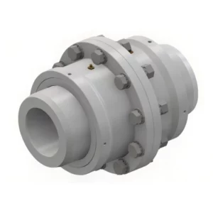
WGC Vertical Installation Drum Shape Gear Coupling
-
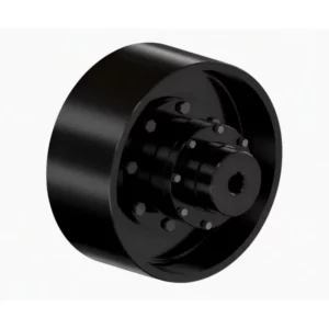
LMZ-II Type Plum Blossom Coupling with Integral Brake Wheel
-
NGCLZ Drum Shape Gear Coupling with Brake Drum | Intermediate Shaft Type
-
WG Drum Shape Gear Coupling
-
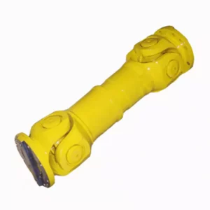
SWP-F Long Large Flexible Universal Joint Couplings
-
WGZ Drum Shape Gear Coupling with Brake Drum