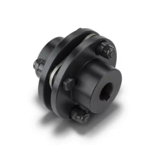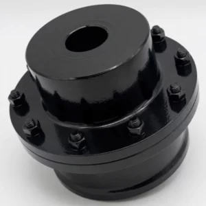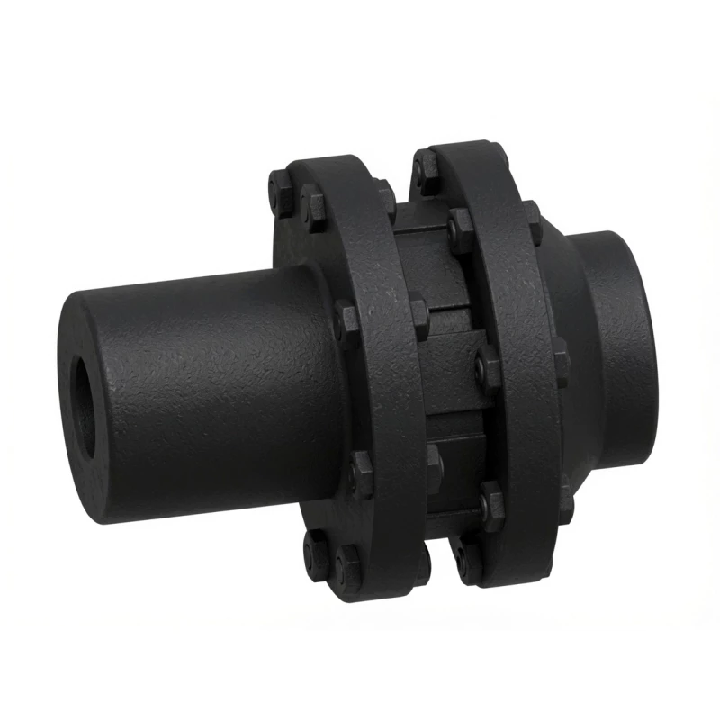
LMS / MLS Type Double-Flange Plum Blossom Jaw Coupling
The LMS / MLS Type Double-Flange Plum Blossom Jaw Coupling (GB/T5272-2002) adds a split double-flange hub design to the standard LM jaw coupling architecture, allowing the polyurethane spider to be replaced without moving either machine. Available in 13 sizes covering 25–25,000 N·m with bore up to 160 mm — the preferred choice for heavy plant, conveyor drives, and any installation where alignment-disturbing maintenance must be avoided.
What Is an LMS / MLS Double-Flange Plum Blossom Coupling?
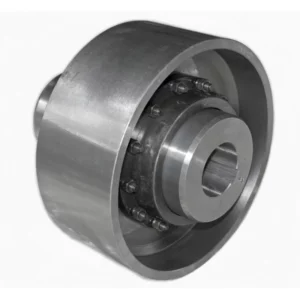
The LMS / MLS double-flange plum blossom jaw coupling solves the single greatest maintenance challenge of standard jaw couplings: the need to move one machine axially to access the spider. By incorporating a split flange ring on one hub, LMS allows the polyurethane spider to be withdrawn and replaced radially — no shaft movement, no realignment, no crane lift required. Manufactured to GB/T5272-2002 (superseding GB5272-85), this design is the go-to choice for heavy industrial installations where downtime cost exceeds coupling cost many times over.
What the Double-Flange Design Changes
In a standard LM coupling, spider replacement requires sliding one hub along its shaft to open the claw gap — straightforward on a motor-pump set but impractical on a drive where both shaft ends are rigidly supported. The LMS hub substitutes a removable outer flange ring for the monolithic hub body. To replace the spider:
- Unbolt the outer flange ring (4–8 bolts depending on size)
- Slide the ring radially to expose the spider lobes
- Extract the worn spider; insert the new polyurethane element
- Replace the flange ring and retorque bolts
Both machines remain in their aligned positions throughout. Total elapsed time: 20–30 minutes for sizes up to LMS8; under 45 minutes for LMS10 and above.
LMS vs LM — Key Differences
| Feature | LM / ML (Basic) | LMS / MLS (Double Flange) |
|---|---|---|
| Spider replacement method | Axial hub slide | Radial flange removal — no shaft movement |
| Machine realignment after maintenance | Required if hub moved | Not required |
| Axial installation space needed | Hub slide clearance required | Standard L0 only |
| Outer diameter (same torque rating) | D | D1 (larger — check clearance) |
| Torque range | 16–8,000 N·m | 25–25,000 N·m |
| Best for | General drives, easy axial access | Fixed-shaft drives, heavy plant, high-maintenance frequency |
LMS / MLS Coupling Specifications & Dimensions
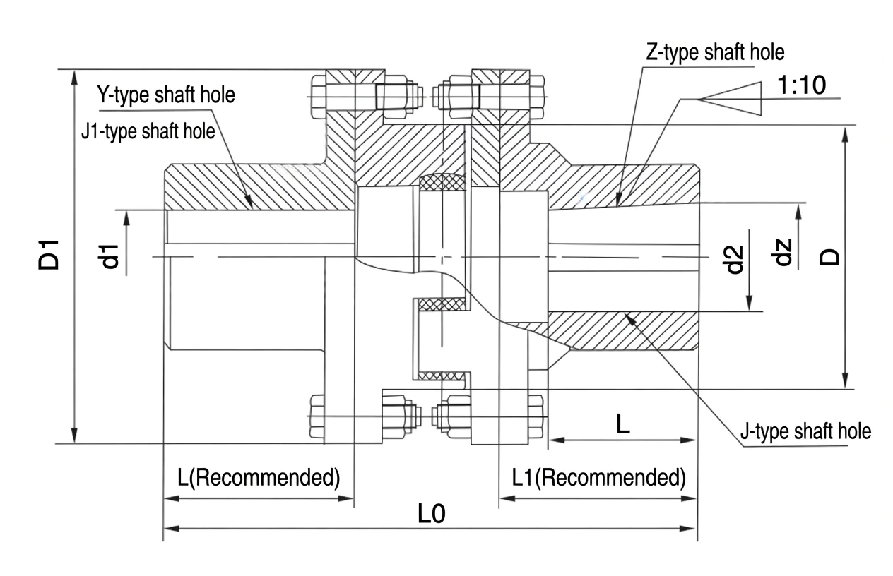
Hub material: cast iron (LMS1–LMS8) / ductile iron (LMS9–LMS13) · Spider: polyurethane −35 °C to +80 °C · a = shA (80±5), b = shD (60±5) hardness codes · * bore compatible with Z / J hole types
| Type (New) |
Old | Nom. Torque N·m (a/b) | Max Speed rpm | Bore d1,d2,dz mm | Bore Length mm | Rec. L,L1 mm | L0 mm | D mm | D1 mm | Spider | ||
|---|---|---|---|---|---|---|---|---|---|---|---|---|
| shA (a) | shD (b) | Y-type L | J1/J/Z L | |||||||||
| LMS1 | MLS1 | 25 | 45 | 8,500 | 12–25 | 32–62 | 27–44 | 35 | 98 | 50 | 90 | MT1 a/b |
| LMS2 | — | 100 | 200 | 6,900 | 20–32 | 52–82 | 38–60 | 40 | 117 | 70 | 110 | MT3 a/b |
| LMS3 | MLS2 | 140 | 280 | 6,200 | 22–40 | 52–112 | 38–84 | 45 | 130 | 85 | 125 | MT4 a/b |
| LMS4 | MLS3 | 350 | 400 | 5,000 | 25–45 | 62–112 | 44–84 | 50 | 150 | 105 | 150 | MT5 a/b |
| LMS5 | MLS4 | 400 | 710 | 4,100 | 30–48 | 82–112 | 60–84 | 55 | 167 | 125 | 185 | MT6 a/b |
| LMS6 | MLS5 | 630 | 1120 | 3,700 | 35*–55 | 82–112 | 60–84 | 60 | 185 | 145 | 205 | MT7 a/b |
| LMS7 | MLS6 | 1120 | 2240 | 3,100 | 45*–65 | 112–142 | 84–107 | 70 | 209 | 170 | 240 | MT8 a/b |
| LMS8 | MLS7 | 1800 | 3550 | 2,800 | 50*–80 | 112–172 | 84–132 | 80 | 240 | 200 | 270 | MT9 a/b |
| LMS9 | MLS8 | 2800 | 5600 | 2,500 | 60*–100 | 142–212 | 107–167 | 90 | 268 | 230 | 305 | MT10 a/b |
| LMS10 | MLS9 | 4500 | 9000 | 2,200 | 70*–120 | 142–212 | 107–167 | 100 | 308 | 260 | 350 | MT11 a/b |
| LMS11 | MLS10 | 6300 | 12500 | 1,900 | 80*–130 | 172–252 | 132–202 | 115 | 345 | 300 | 400 | MT12 a/b |
| LMS12 | MLS11 | 11200 | 20000 | 1,600 | 90*–130 | 172–252 | 132–202 | 125 | 373 | 360 | 460 | MT13 a/b |
| LMS13 | MLS12 | 12500 | 25000 | 15,000 | 100*–160 | 212–302 | 167–242 | 135 | 383 | 400 | 500 | MT14 a/b |
L0 is total coupling length when both shaft holes use the recommended L value. * bore diameters compatible with Z/J hole types. a/b = hardness code pair for each size.
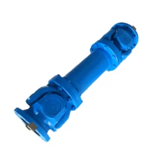
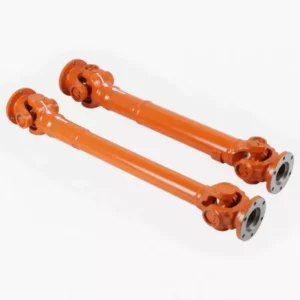
Plum Blossom Coupling Family — Related Types
All multiple types share the same polyurethane spider grades and GB/T5272-2002 bore standards. Browse the full range on our coupling catalogue.
Torque: 16–8,000 N·m · Spider: axial slide replacement · General drives
Torque: 25–25,000 N·m · Spider: radial replacement, no machine movement
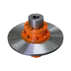
Torque: 250–25,000 N·m · Integrated split drum · Shoe-brake applications
Torque: 250–12,500 N·m · One-piece brake hub · Compact drum-brake drives
Torque: 630–1,800 N·m nominal · Disc brake systems · Spider replaceable in situ
How to Select the Right LMS / MLS Size
Design Torque Formula
Select the LMS size whose nominal torque Tn ≥ TC, then confirm shaft bore diameters fall within the listed bore range. Because the LMS outer diameter D1 is larger than the equivalent LM size, also verify radial clearance in the drive housing before specifying.
When to Choose LMS over LM
- Both shaft ends are rigidly supported (e.g., gearbox output to pump with close-coupled bearing housing)
- Machine realignment is expensive, time-consuming, or requires specialist equipment
- The drive is in continuous production and unplanned spider failure must be corrected in the shortest possible time
- The application has high shock or load reversals that shorten spider life, making frequent replacement inevitable
Spider Hardness Selection
| Grade Code | Shore | Best For |
|---|---|---|
| a (shA) | 80±5 | General purpose — default selection for most heavy drives |
| b (shD) | 60±5 | Maximum damping — paper machines, printing lines, precision drives |
Note: the LMS series uses hardness codes a/b (not shA/shB/shD). Code a = shA (80±5); code b = shD (60±5).
Industry Applications
Large dryer-section drives (LMS8–LMS12) suffer frequent spider wear from moisture, heat, and torque pulsation. The radial-replacement design means a spider swap during a scheduled roll change takes under 30 minutes versus 3+ hours of realignment with standard couplings.
Kiln auxiliary drives and bucket-elevator gearboxes (LMS10–LMS13) experience high shock loads. Replacing the spider without disturbing the precision alignment of the kiln trunnion drive is a critical operational advantage.
Crane slewing drives and winch gearboxes at port facilities run the LMS series for its ability to service the coupling without disturbing the drive train. Marine-grade corrosion protection is available on request.
Cooling tower fan drives and auxiliary pump sets at power stations (LMS5–LMS9). Plant operators value the ability to change spiders during planned outage windows without requiring laser realignment afterwards.
Rolling mill auxiliary drives and continuous caster drives use LMS couplings because the heavy structural frames make axial hub movement impractical and re-alignment after any maintenance takes hours of precision work.
Large Pump Stations
Multi-stage booster pump sets with close-coupled gearboxes (LMS6–LMS10). The double-flange design eliminates the risk of disturbing pump seal alignment during spider replacement — a common cause of premature seal failure with standard couplings.
For drives requiring an integrated brake, explore our LMZ-I and LMZ-II brake-wheel coupling pages.
Installation & Maintenance
Initial Installation
- Hub fitting: Press or heat-shrink both inner hubs onto their shafts. Torque all setscrews to specification.
- Alignment: Align shafts to within angular (≤2°) and radial tolerances using dial indicator or laser. This is the only time alignment is required over the coupling's service life — make it count.
- Spider insertion: Slide the polyurethane spider between the claw faces radially from the flange side.
- Flange ring: Fit and bolt the outer flange ring; torque bolts evenly in a cross-pattern to the specified value.
- Verification: Rotate by hand; confirm even spider contact, no pinching, correct L0 gap.
In-Service Spider Replacement
No shaft movement required at any point in this procedure:
- De-energise and lock out the drive.
- Remove the outer flange ring bolts; withdraw the ring radially.
- Extract the worn spider from between the claw faces.
- Inspect claw faces for wear or damage; replace hub if claw wear exceeds 1.5 mm depth.
- Insert the new spider element radially; replace flange ring and torque bolts to specification.
- Re-energise; monitor for 10 minutes at no load before returning to service.
Inspection interval: Every 6–12 months under normal conditions. For high-shock duty (K ≥ 2.5) inspect every 3–4 months.
LMS vs Comparable Coupling Solutions
| Criterion | LMS Double Flange | LM Basic | JS Grid Coupling |
|---|---|---|---|
| Spider/element replacement | Radial, no movement | Axial hub slide | Partial disassembly |
| Lubrication | None | None | Grease required |
| Vibration damping | ★★★★☆ | ★★★★☆ | ★★★☆☆ |
| Max torque (standard) | 25,000 N·m | 8,000 N·m | High |
| OD for same torque | Larger (flange ring) | Compact | Compact (cased) |
| Relative cost | Medium | Low–Medium | Medium–High |
Customer Case Studies
Australia — Pulp & Paper Mill
Switched to LMS9 on four dryer-section drives. First spider change took 28 minutes without touching either machine — compared to a half-day job with our previous coupling type. We've now standardised LMS across the entire mill. The saving in realignment labour has paid for the coupling premium many times over.
Maintenance Superintendent, Victoria AU
★★★★★
United Kingdom — Cement Plant
LMS12 couplings on kiln auxiliary drive gearboxes. Twelve months in, zero unplanned stoppages attributable to the coupling. The shA spider handled the kiln's shock loads well. Spider swaps during scheduled kiln stops now take one shift instead of three.
Reliability Engineer, West Midlands UK
★★★★★
Japan — Steel Rolling Mill
Installed LMS10/LMS11 on continuous caster auxiliary drives. The combination of radial spider replacement and the higher torque ceiling (vs the LM series) was decisive for our application. Dimensional drawings were accurate; delivery matched the quoted schedule.
Mechanical Engineer, Aichi Prefecture JP
★★★★☆
Canada — Large Pump Station
Six LMS8 units on multi-stage booster pump sets. We had chronic seal failures with a standard coupling because axial hub movement during maintenance was disturbing the pump seal alignment. Since switching to LMS, zero seal callouts in fourteen months.
Operations Manager, Alberta CA
★★★★★
Frequently Asked Questions
▶ What makes the LMS different from the LM jaw coupling?
The LMS incorporates a split removable flange ring on one hub. Unbolting and withdrawing this ring radially opens the claw gap without any axial movement of the hub — allowing the spider to be extracted and replaced with both machines remaining in their aligned positions. The LM basic type requires one hub to be slid axially, which may disturb precision alignment.
▶ Can the LMS spider really be replaced without any shaft movement?
Yes. The entire procedure — remove flange bolts, slide ring radially, extract spider, insert new spider, replace ring, torque bolts — involves zero axial movement of either hub. Both shafts remain in their installed positions throughout, preserving alignment integrity.
▶ What hardness codes do LMS couplings use?
LMS uses codes a and b. Code a corresponds to shA (Shore 80±5) — the general-purpose grade. Code b corresponds to shD (Shore 60±5) — the softer high-damping grade. The stiffer shB (92±5) is not offered in the LMS range.
▶ How does LMS13 reach 25,000 N·m when LM13 only reaches 8,000 N·m?
The LMS13 hub OD (D1 = 500 mm) is significantly larger than LM13 (D = 400 mm), accommodating a larger spider element (MT14) with higher torque capacity. The double-flange architecture also distributes claw forces differently across the flange interface, enabling the higher rating.
▶ What is the recommended torque for flange ring bolts?
Bolt torque varies by size — refer to the installation datasheet supplied with each coupling. As a guide, LMS1–LMS5 flange bolts are M8–M12 grade 8.8; LMS8–LMS13 use M16–M20 grade 10.9. Always torque in a cross-pattern in three incremental passes to ensure even spider compression.
Specify LMS / MLS Couplings for Your Next Project
GBC supplies all 13 LMS sizes with full dimensional documentation, bore customisation, and both spider hardness grades. Minimum order: one piece. Request a quote and our engineering team will confirm dimensional compatibility and lead time within 24 hours.
The LMS / MLS Type Double-Flange Plum Blossom Jaw Coupling (GB/T5272-2002) adds a split double-flange hub design to the standard LM jaw coupling architecture, allowing the polyurethane spider to be replaced without moving either machine. Available in 13 sizes covering 25–25,000 N·m with bore up to 160 mm — the preferred choice for heavy plant, conveyor drives, and any installation where alignment-disturbing maintenance must be avoided.