JS Shell Radial Mount Grid Coupling
The JS Shell Radial Mount Grid Coupling provides dependable torque transmission ranging from 45 to 800,000 N·m, engineered with serpentine spring technology for superior vibration damping. Its radial-access shell enables fast spring replacement without displacing connected machinery, making it ideal for heavy-duty industrial power transmission.
JS Shell Radial Mount Grid Coupling – Serpentine Spring Power Transmission Solution
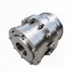
The JS Shell Radial Mount Grid Coupling is a precision-engineered metallic flexible coupling that utilizes serpentine spring elements to transmit torque between rotating shafts. Designed for radial shell installation, this coupling allows maintenance crews to access and replace the spring elements by simply removing the radial shell halves – without the need to move motors, gearboxes, or other connected equipment along the shaft axis.
Covering a torque capacity spectrum from 45 N·m up to 800,000 N·m across 25 standardized sizes (JS1 through JS25), the JS radial mount grid coupling serves a vast range of applications in mining, metallurgy, power generation, petrochemical processing, and general manufacturing. The serpentine spring design achieves an average vibration damping rate of 36%, a transmission efficiency of 99.47%, and a short-duration overload capacity equal to twice the rated torque.
Key Features and Performance Advantages
High Torque Capacity
Spanning 25 models from JS1 (45 N·m) to JS25 (800,000 N·m), these couplings accommodate shaft bore diameters from 18 mm to 500 mm, fitting virtually any industrial drive train.
Superior Vibration Damping
The serpentine spring absorbs torsional vibrations through controlled elastic deformation, delivering an average damping ratio of 36% – significantly outperforming rigid and most elastomeric couplings.
99.47% Transmission Efficiency
Minimal energy loss through the spring element ensures near-unity power transfer, reducing operating costs and heat generation in continuous-duty applications.
Radial Shell Access
The two-piece radial shell can be removed perpendicular to the shaft axis, granting full access to the serpentine spring for inspection or replacement without disturbing shaft alignment.
2x Overload Tolerance
Engineered to withstand short-term overloads of up to twice the nominal torque rating, providing a critical safety margin during start-up surges and transient load spikes.
Modular Assembly
Compact construction with few parts – two half-couplings, one radial shell, one serpentine spring, and seals – simplifies stocking, assembly, and field maintenance across all 25 sizes.
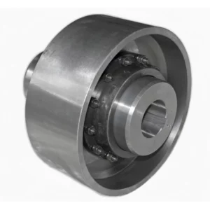
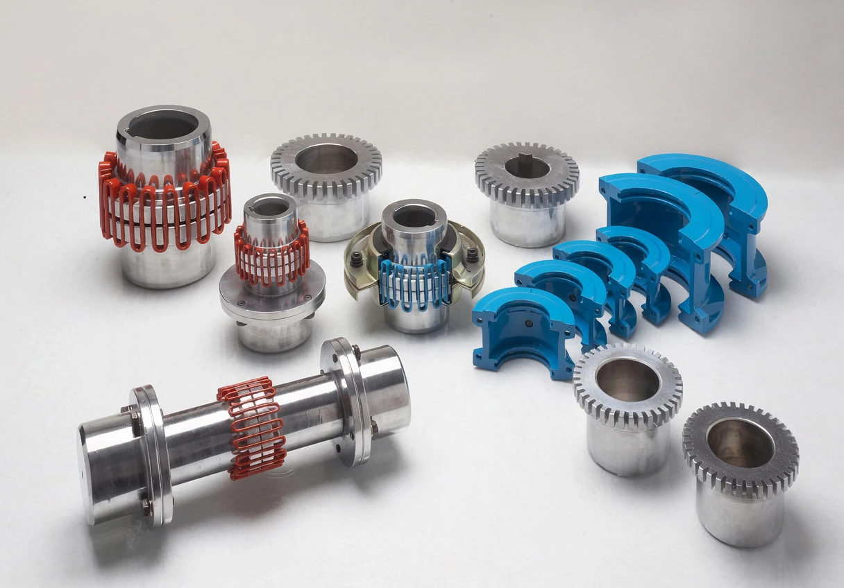
Structural Design and Component Breakdown
The JS radial mount grid coupling consists of five principal components working in unison to transmit torque while accommodating shaft misalignment:
1 & 5 – Half Couplings (Hub Halves): Precision-machined hubs that mount on the driving and driven shafts via keyway connections. Available in a wide range of bore diameters with standard keyway profiles (Type A and Type B).
2 – Radial Shell (Cover): A two-piece housing that encloses the serpentine spring and retains lubricant. Models JS1 through JS22 use aluminum alloy shells for lighter weight, while JS23 through JS25 use steel shells for higher structural strength.
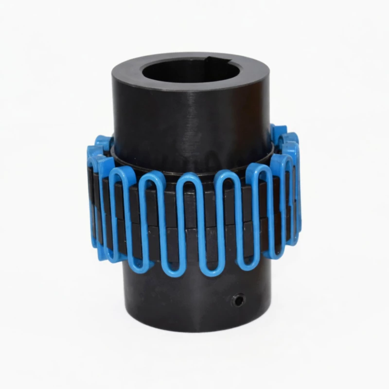
3 – Serpentine Spring: The core flexible element, manufactured from premium spring steel with rigorous heat treatment for optimal elasticity, fatigue resistance, and mechanical durability. The spring engages with tooth profiles on both hub halves.
4 – Lubrication Port: A dedicated grease fitting that allows periodic relubrication without disassembly, extending the coupling service life.
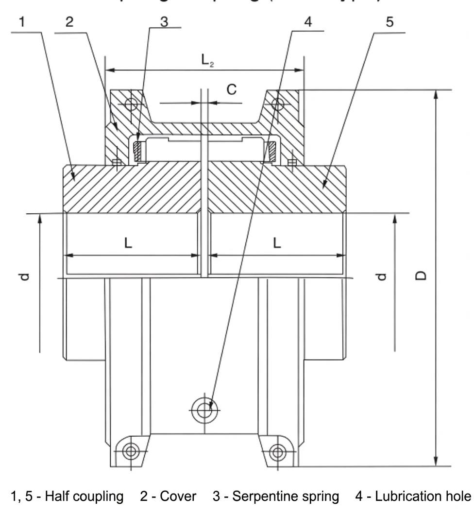
Fig. 1 – JS radial mount grid coupling: structural cross-section and principal dimensions
During operation, the serpentine spring sits within the alveolar (tooth) grooves of both half-couplings. Torque is transferred through the circumferential spring force acting on the tooth faces. When torsional misalignment occurs, the spring deforms elastically, preventing resonance while reducing transmitted vibration. This mechanism extends the service life far beyond that of non-metallic flexible element couplings. For further guidance on coupling solutions for industrial drives, visit our main catalog.
Technical Specifications – JS Radial Mount Grid Coupling (Full Range)
The table below lists all 25 standard sizes with complete dimensional and performance parameters. All dimensions are in millimeters (mm) unless noted otherwise. Shaft bore can be customized to client specifications.
| Model (New) | Model (Legacy) | Nominal Torque Tn (N·m) |
Max Speed (rpm) |
Shaft Bore d (mm) | Bore Length L (mm) |
L₂ (mm) | D (mm) | D₁ (mm) | Clearance C (mm) |
Weight (kg) |
Moment of Inertia J (kg·m²) |
Lubricant (kg) |
|---|---|---|---|---|---|---|---|---|---|---|---|---|
| JS1 | JS101 | 45 | 4500 | 18, 19, 20, 22, 24, 25, 28 | 47 | 66 | 95 | – | 3 | 1.91 | 0.00141 | 0.0272 |
| JS2 | JS102 | 140 | 4500 | 22, 24, 25, 28, 30, 32, 35 | 47 | 68 | 105 | – | 3 | 2.59 | 0.00223 | 0.0408 |
| JS3 | JS103 | 224 | 4500 | 25, 28, 30, 32, 35, 38, 40, 42 | 50 | 70 | 115 | – | 3 | 3.36 | 0.00327 | 0.0544 |
| JS4 | JS104 | 400 | 4500 | 32, 35, 38, 40, 42, 45, 48, 50 | 60 | 80 | 130 | – | 3 | 5.45 | 0.00727 | 0.068 |
| JS5 | JS105 | 630 | 4350 | 40, 42, 45, 48, 50, 55, 56 | 63 | 92 | 150 | – | 3 | 7.26 | 0.0119 | 0.0862 |
| JS6 | JS106 | 900 | 4125 | 48, 50, 55, 56, 60, 63, 65 | 76 | 95 | 160 | – | 3 | 10.44 | 0.0185 | 0.113 |
| JS7 | JS107 | 1,800 | 3600 | 55, 56, 60, 63, 65, 70, 71, 75, 80 | 89 | 116 | 190 | – | – | 17.7 | 0.0451 | 0.172 |
| JS8 | JS108 | 3,150 | 3600 | 65, 70, 71, 75, 80, 85, 90, 95 | 98 | 122 | 210 | – | – | 25.42 | 0.0787 | 0.254 |
| JS9 | JS109 | 5,600 | 2440 | 75, 80, 85, 90, 95, 100, 110 | 120 | 155 | 250 | – | 5 | 42.22 | 0.178 | 0.426 |
| JS10 | JS110 | 8,000 | 2250 | 85, 90, 95, 100, 110, 120 | 127 | 162 | 270 | – | 5 | 54.45 | 0.27 | 0.508 |
| JS11 | JS111 | 12,500 | 2025 | 90, 95, 100, 110, 120, 125, 130, 140 | 149 | 192 | 310 | – | – | 81.27 | 0.514 | 0.735 |
| JS12 | JS112 | 18,000 | 1800 | 110, 120, 125, 130, 140, 150, 160, 170 | 162 | 195 | 346 | – | – | 121 | 0.989 | 0.908 |
| JS13 | JS113 | 25,000 | 1650 | 120, 125, 130, 140, 150, 160, 170, 180, 190, 200 | 184 | 201 | 384 | – | – | 178 | 1.85 | 1.135 |
| JS14 | JS114 | 35,500 | 1500 | 140, 150, 160, 170, 180, 190, 200 | 183 | 271 | 450 | 391 | 6 | 234.26 | 3.49 | 1.952 |
| JS15 | JS115 | 50,000 | 1350 | 160, 170, 180, 190, 200, 220, 240 | 198 | 279 | 500 | 431 | 6 | 316.89 | 5.82 | 2.815 |
| JS16 | JS116 | 63,000 | 1225 | 180, 190, 200, 220, 240, 250, 260, 280 | 216 | 304 | 566 | 487 | 6 | 448.1 | 10.4 | 3.496 |
| JS17 | JS117 | 90,000 | 1100 | 200, 220, 240, 250, 260, 280, 300 | 239 | 322 | 630 | 555 | 6 | 619.71 | 18.3 | 3.76 |
| JS18 | JS118 | 125,000 | 1050 | 240, 250, 260, 280, 300, 320 | 260 | 356 | 675 | 608 | 6 | 776.34 | 26.1 | 4.4 |
| JS19 | JS119 | 160,000 | 900 | 280, 300, 320, 340, 360 | 280 | 355 | 756 | 660 | – | 1,058.27 | 43.5 | 5.63 |
| JS20 | JS120 | 224,000 | 820 | 300, 320, 340, 360, 380 | 305 | 432 | 845 | 751 | – | 1,425.56 | 75.5 | 10.53 |
| JS21 | JS121 | 315,000 | 730 | 320, 340, 360, 380, 400, 420 | 325 | 490 | 920 | 822 | – | 1,786.49 | 113 | 16.07 |
| JS22 | JS122 | 400,000 | 680 | 340, 360, 380, 400, 420, 440, 450 | 345 | 546 | 1000 | 905 | – | 2,268.64 | 175 | 24.06 |
| JS23 | JS123 | 500,000 | 630 | 360, 380, 400, 420, 440, 450, 460, 480 | 368 | 648 | 1087 | – | 13 | 2,950.82 | 339 | 33.82 |
| JS24 | JS124 | 630,000 | 580 | 400, 420, 440, 450, 460 | 401 | 698 | 1180 | – | – | 3,836.3 | 524 | 50.17 |
| JS25 | JS125 | 800,000 | 540 | 420, 440, 450, 460, 480, 500 | 432 | 762 | 1260 | – | – | 4,686.19 | 711 | 67.24 |
Note: Weight calculated without bore holes. Shaft bores can be manufactured to customer requirements. For sizes JS1–JS22, the shell is aluminum alloy; JS23–JS25 use steel shells.
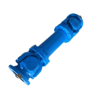
Working Principle
The JS grid coupling operates through the axial engagement of a continuous serpentine spring element within the tooth grooves machined into each half-coupling hub. When the driving shaft rotates, the spring transmits torque by pressing against the tooth flanks of both hubs simultaneously. Under torsional or angular misalignment, the spring undergoes controlled elastic deformation rather than transmitting shock loads rigidly.
This elastic engagement mechanism serves three critical functions: first, it prevents torsional resonance by introducing a tunable stiffness between the connected machines; second, it absorbs start-up shock loads, protecting gearboxes, bearings, and driven equipment; third, it compensates for radial, angular, and axial shaft misalignment within published tolerances. The result is a mechanical system with measurably lower vibration, extended bearing life, and reduced downtime.
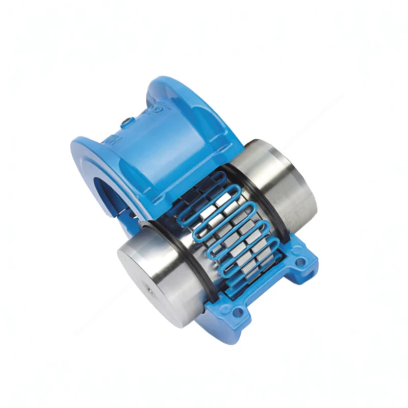
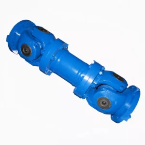
Fig. 2 – JS grid coupling: complete radial mount assembly
Industry Applications
The JS Shell Radial Mount Grid Coupling is widely deployed across industries where reliable torque transmission and vibration control are essential:
Mining & Minerals
Driving ball mills, crushers, conveyors, and screening equipment where shock loads and dusty conditions demand rugged, maintainable couplings.
Steel & Metallurgy
Connecting rolling mill drives, continuous caster equipment, and overhead crane hoists subjected to extreme torsional reversals and thermal cycling.
Power Generation
Coupling turbines to generators, and driving auxiliary systems such as induced-draft fans, boiler feed pumps, and coal pulverizers in thermal power plants.
Cement & Building Materials
Powering rotary kilns, vertical mills, and clinker cooler drives that operate under heavy sustained loads with frequent start-stop cycles.
For a comprehensive overview of all available coupling types, browse the complete GBC industrial coupling catalog.
Selection and Calculation Guide
Proper coupling selection requires matching the calculated torque (Tc) to the nominal torque (Tn) of the coupling, while ensuring the shaft bore diameter and operating speed fall within the specified ranges.
Step 1: Calculate Design Torque
Use the formula: Tc = K × 9550 × Pw / n, where Pw is the drive power in kW, n is the working speed in rpm, and K is the service factor based on the prime mover and driven machine classification. The calculated torque Tc must not exceed the nominal torque Tn of the chosen coupling size.
Step 2: Service Factor (K) Reference
| Prime Mover | Class I | Class II | Class III | Class IV | Class V | Class VI |
|---|---|---|---|---|---|---|
| Electric Motor / Steam Turbine | 2.3 | 2.7 | 3 | 3.4 | 4.1 | 5.6 |
| ICE – 6+ Cylinders | 2.8 | 3.2 | 3.5 | 3.6 | 4.6 | 6.1 |
| ICE – 4 or 5 Cylinders | 3.3 | 3.7 | 4 | 4.4 | 5.1 | 6.6 |
| ICE – 2 Cylinders | 3.6 | 4 | 4.3 | 4.7 | 5.4 | 6.9 |
| ICE – 1 Cylinder | 4 | 4.4 | 4.7 | 5.1 | 5.8 | 7.3 |
Driven Machine Classes: I – Centrifugal pumps, small generators, belt conveyors, fans, liquid mixers. II – Turbine compressors, woodworking machinery, transport equipment. III – Mixers, reciprocating pumps, flywheel compressors, punch presses. IV – Weaving machines, cement mixers, tractors, hoists. V – Paper machinery, excavators, cranes, crushers, blowers. VI – Rolling mills, no-flywheel piston pumps, heavy blooming mills.
Step 3: Verify Shaft Bore and Speed
After selecting a coupling whose Tn ≥ Tc, verify that the required shaft bore diameter falls within the available bore range for that model, and that the operating speed does not exceed the permissible rotational speed. If both the bore and torque requirements cannot be satisfied by a single model, choose the next larger size that satisfies both criteria.
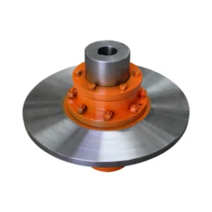
GBC grid coupling product range – engineered for reliability across all industrial sectors
Customer Reviews & Project References
★★★★★ – Mining Operation, Australia
Industry: Coal Mining | Application: Conveyor Drive
“We installed JS14 couplings on three overland conveyor drives carrying 2,400 tonnes per hour. After 18 months of continuous service, vibration readings at the gearbox bearings decreased by 28% compared to the previous elastomeric couplings. Spring replacement during a scheduled shutdown took our fitters less than 90 minutes per coupling – no shaft realignment required.”
– Maintenance Manager, Hunter Valley Mine
★★★★★ – Steel Mill, Germany
Industry: Metallurgy | Application: Rolling Mill Main Drive
“Our continuous hot strip mill demanded a coupling that could absorb severe torsional reversals at 90,000 N·m. The JS17 grid coupling has operated faultlessly through over 6,000 rolling campaigns. The 2x overload tolerance gave us peace of mind during cobble recovery events.”
– Chief Mechanical Engineer, Duisburg Steel Works
★★★★☆ – Cement Plant, India
Industry: Cement Manufacturing | Application: Vertical Roller Mill
“We standardized on JS12 couplings for our vertical roller mill auxiliary drives after experiencing repeated failures with jaw couplings. The grid coupling handled the high start-up inertia loads without any spring degradation over two monsoon cycles. Lubrication intervals are manageable at 3,000 operating hours.”
– Plant Engineering Head, Gujarat Cement Ltd.
Frequently Asked Questions
Partner With GBC – Your Trusted Grid Coupling Supplier
Whether you need a single replacement coupling or a full project supply of 200+ units, GBC delivers factory-direct JS grid couplings with competitive pricing, custom bore machining, and global logistics support. All couplings ship with material certificates, dimensional inspection reports, and a standard 12-month warranty.
Request a Quotation
Browse All Couplings
Typical response time: within 24 business hours | Custom bores available
The JS Shell Radial Mount Grid Coupling provides dependable torque transmission ranging from 45 to 800,000 N·m, engineered with serpentine spring technology for superior vibration damping. Its radial-access shell enables fast spring replacement without displacing connected machinery, making it ideal for heavy-duty industrial power transmission.