JSJ Intermediate Shaft Grid Coupling
The JSJ Intermediate Shaft Grid Coupling connects two machines separated by a significant axial distance using a rigid intermediate shaft between two grid coupling assemblies. Available in 16 sizes from 140 to 160,000 N·m, it is the solution for long-span drive trains in pipeline pumps, tunnel ventilation fans, and multi-machine production lines.
JSJ Intermediate Shaft Grid Coupling – Long-Span Serpentine Spring Coupling With Spacer Shaft
The JSJ Intermediate Shaft Grid Coupling addresses the engineering challenge of connecting two machines that are separated by a distance too great for a standard single-body coupling. By inserting a rigid intermediate (spacer) shaft between two complete grid coupling assemblies, the JSJ bridges axial gaps while maintaining the full torsional damping, misalignment compensation, and overload protection of the serpentine spring mechanism at both connection points.
Available in 16 sizes from JSJ1 (140 N·m) to JSJ16 (160,000 N·m), this coupling type is specified whenever the distance between driving and driven shaft ends exceeds the capacity of a single coupling body. The intermediate shaft diameter (d₁) is pre-determined for each model to ensure torsional rigidity across the span, while the minimum intermediate shaft length (L₃min) defines the shortest usable spacer configuration.
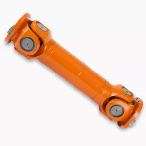
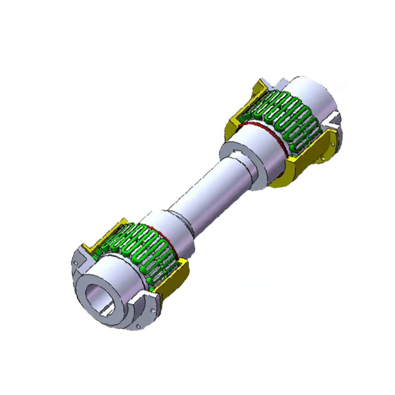
Fig. 1 – JSJ Intermediate Shaft Grid Coupling product assembly
Long-Span Engineering Advantages
Bridges Extended Shaft Gaps
Connects machines separated by distances that single-body couplings cannot span, with intermediate shaft lengths customizable to the installation layout.
Dual Misalignment Compensation
With a grid coupling assembly at each end, the JSJ compensates for misalignment independently at both the driving and driven connections – doubling the system tolerance.
Dual Vibration Damping Points
Two serpentine spring elements, one at each end, provide compounded torsional vibration absorption along the entire drive train length.
Drop-Out Maintenance
The intermediate shaft can be removed axially without disturbing the hub positions on either machine, enabling coupling service without moving the connected equipment.
16 Sizes to 160,000 N·m
Full industrial torque coverage from small auxiliary drives to large turbine-generator sets and pipeline compressor trains.
Pre-Balanced Assembly
The intermediate shaft and both hub pairs can be dynamically balanced as a complete assembly, minimizing vibration in high-speed long-span applications.
Component Architecture
The JSJ coupling consists of six principal components:
1 – Intermediate Shaft: A precision-machined steel shaft of diameter d₁ that spans the gap between the two machines. The minimum length L₃min is specified per model; longer shafts are manufactured to order.
2 – Half Couplings (Hubs): Four hubs total – two mount on the driving and driven machine shafts, and two mount on the intermediate shaft ends. All hubs feature the standard grid coupling tooth profile.
3 – Serpentine Springs: Two spring elements, one at each coupling joint, providing independent torsional flexibility and damping at both connections.
4 – Lubrication Ports: Each coupling body has its own lubrication fitting for independent re-greasing schedules.
5 – Shells (Covers): Two shells, one enclosing each spring, retaining lubricant and protecting the springs from environmental contamination.
6 – Connecting Flanges: At each end of the intermediate shaft, flanged connections secure the shaft to the adjacent hub pairs with precision bolt circles.
For standard single-span coupling needs, see the JS grid coupling series. The JSJ is specified only when the shaft gap exceeds the capacity of standard coupling variants.
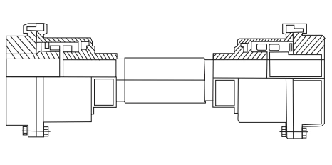
Fig. 2 – JSJ Intermediate Shaft Grid Coupling cross-section and dimensional drawing
Technical Specifications – JSJ Intermediate Shaft Grid Coupling
Complete specifications for all 16 JSJ sizes. Weight and lubricant quantities shown are per coupling end (one side); multiply by 2 for the complete assembly.
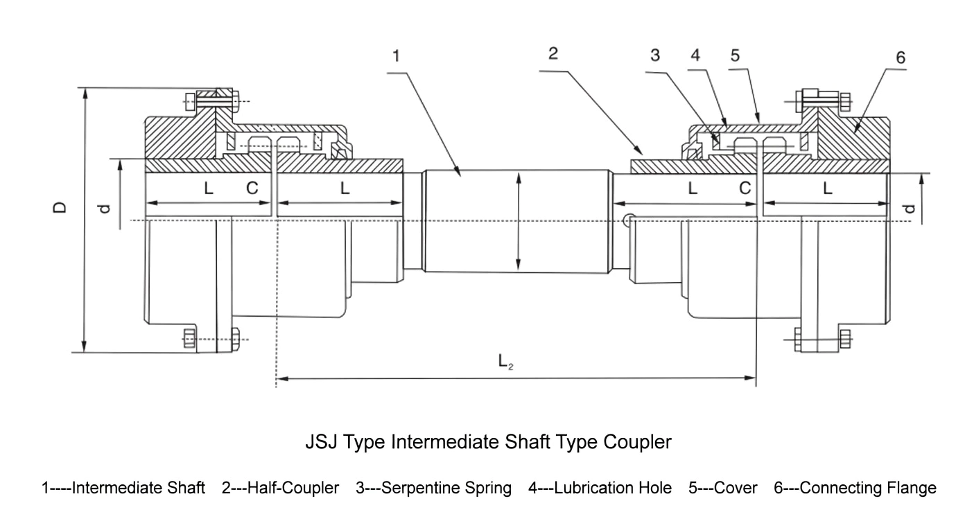
Fig. 3 – JSJ Intermediate Shaft Grid Coupling complete dimensional reference
| Model | Nominal Torque Tn (N·m) |
Shaft Bore d (mm) | Intermediate Shaft d₁ (mm) |
Bore Length L (mm) |
Min Intermediate Length L₃min (mm) |
D (mm) | L₂ (mm) | C (mm) | Weight per End (kg) |
Lubricant per End (kg) |
|---|---|---|---|---|---|---|---|---|---|---|
| JSJ1 | 140 | 22, 24, 25, 28, 30, 32, 35 | 28 | 48 | 162 | 116 | 78 | 3 | 3.9 | 0.04 |
| JSJ2 | 400 | 32, 35, 38, 40, 42, 45, 48, 50 | 35 | 60 | 195 | 158 | 94 | 3 | 8.85 | 0.06 |
| JSJ3 | 900 | 48, 50, 55, 56, 60, 63, 65 | 50 | 76 | 213 | 183 | 103 | 3 | 15.62 | 0.111 |
| JSJ4 | 1,800 | 55, 56, 60, 63, 65, 70, 71, 75, 80 | 63 | 89 | 275 | 218 | 134 | 3 | 26.42 | 0.172 |
| JSJ5 | 3,150 | 65, 70, 71, 75, 80, 85 | 75 | 98 | 294 | 245 | 144 | 3 | 37.23 | 0.254 |
| JSJ6 | 5,600 | 75, 80, 85, 90, 95, 100, 110 | 90 | 120 | 372 | 286 | 182 | 5 | 63.11 | 0.427 |
| JSJ7 | 8,000 | 80, 85, 90, 95, 100, 110, 120 | 100 | 127 | 391 | 324 | 191 | 5 | 83.54 | 0.508 |
| JSJ8 | 12,500 | 90, 95, 100, 110, 120, 125, 130, 140 | 120 | 150 | 453 | 327 | 220 | – | 98 | 0.735 |
| JSJ9 | 18,000 | 110, 120, 125, 130, 140, 150, 160, 170 | 130 | 162 | 463 | 365 | 225 | – | 140.29 | 0.908 |
| JSJ10 | 25,000 | 120, 125, 130, 140, 150, 160, 170, 180, 190, 200 | 140 | 184 | 482 | 419 | 235 | – | 209.75 | 1.135 |
| JSJ11 | 35,500 | 140, 150, 160, 170, 180, 190, 200 | 160 | 183 | 549 | 478 | 268 | – | 276.94 | 1.952 |
| JSJ12 | 50,000 | 160, 170, 180, 190, 200, 220, 240 | 198 | 200 | 587 | 548 | 287 | 6 | 381.36 | 2.815 |
| JSJ13 | 63,000 | 180, 190, 200, 220, 240, 250 | 216 | 200 | 622 | 604 | 305 | 6 | 519.38 | 3.496 |
| JSJ14 | 90,000 | 200, 220, 240, 250, 260, 280 | 220 | 200 | 673 | 665 | 330 | 6 | 718.68 | 3.768 |
| JSJ15 | 125,000 | 240, 250, 260, 280, 300, 320 | 250 | 200 | 711 | 708 | 350 | 6 | 898.47 | 4.4 |
| JSJ16 | 160,000 | 280, 300, 320, 340, 360 | 280 | 200 | 744 | 782 | 366 | 6 | 1,205.28 | 5.62 |
Note: Weight per end calculated without bore holes. Total coupling assembly weight = 2x listed weight plus intermediate shaft weight. Intermediate shaft lengths customizable beyond L3min to suit installation requirements.
Primary Application Sectors
Pipeline Pumping Stations
Connecting electric motors to pipeline booster pumps separated by thrust blocks, isolation valves, or structural walls that mandate extended shaft spans.
Tunnel Ventilation Systems
Driving large axial fans mounted inside tunnel bores from motors positioned outside the tunnel envelope, where intermediate shaft lengths of 2–5 meters are typical.
Multi-Stage Compressor Trains
Linking multi-body compressor stages that require maintenance access gaps between casings, with the intermediate shaft bridging the service clearance.
Ship Engine Room Layouts
Connecting main engines to reduction gearboxes in vessel engine rooms where the engine and gearbox are separated by structural bulkheads or equipment platforms.
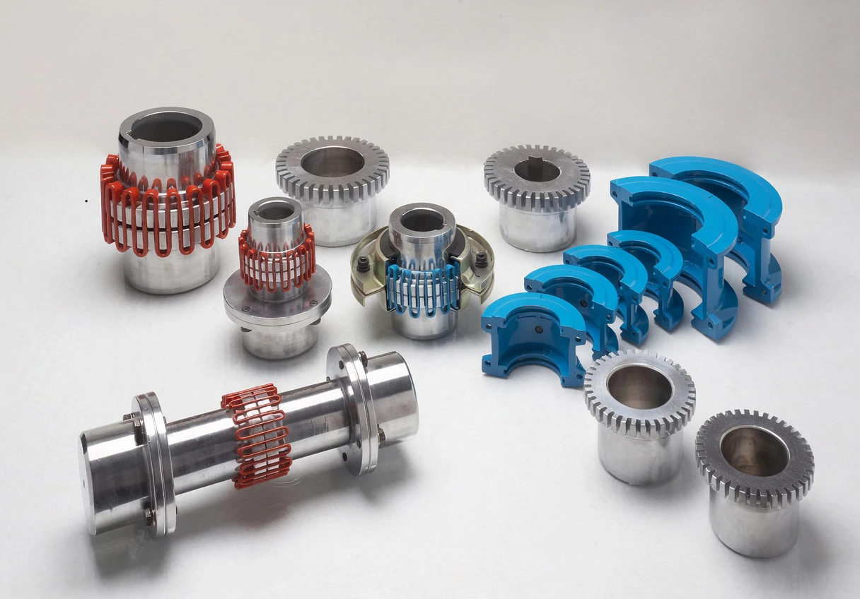
GBC grid coupling product range – engineered for reliability across all industrial sectors
Customer Experiences
★★★★★ – Pipeline Station, Russia
Industry: Oil & Gas | Application: Crude Pipeline Booster Pump
“We specified JSJ14 couplings for six 90,000 N·m crude oil booster pump sets. The 1.8-meter intermediate shaft spans the concrete thrust block between motor and pump. Both coupling ends absorb the torsional pulsation from the positive-displacement pumps, and bearing vibration at both machines dropped to ISO 10816 Zone A after commissioning.”
– Pipeline Engineering Director, Western Siberia Trunk Line
★★★★★ – Sugar Factory, Thailand
Industry: Food & Agriculture | Application: Cane Mill Drive
“Our cane mills require coupling spans of 1.2 meters between the steam turbine and the first mill roller gearbox. The JSJ6 intermediate shaft couplings replaced a rigid spacer arrangement that was transmitting damaging torsional shocks to our gearbox. Mill gearbox repair frequency has reduced from twice per season to zero over the past three crushing campaigns.”
– Chief Mechanical Engineer, Udon Thani Sugar Complex
★★★★☆ – Water Authority, Egypt
Industry: Water Infrastructure | Application: Large Axial Flow Pump
“We installed JSJ10 couplings on four 25,000 N·m axial flow drainage pumps with 2.5-meter intermediate shafts. The dual damping points keep vibration levels acceptable even at variable-speed operation down to 60% rated speed. We would value a stainless steel intermediate shaft option for our high-humidity pump house environment.”
– Pumping Station Manager, Nile Delta Drainage Authority
Frequently Asked Questions
Source JSJ Intermediate Shaft Couplings From GBC
GBC engineers and manufactures complete JSJ intermediate shaft grid coupling assemblies including custom-length intermediate shafts, precision bore machining on all four hubs, dynamic balancing of the complete rotating assembly, and full dimensional certification. From pipeline stations to tunnel ventilation projects, every JSJ shipment includes installation drawings, alignment guidelines, and a 12-month warranty.
Request a JSJ Configuration Quote
Browse All Coupling Solutions
Response within 24 hours | Custom bores available
The JSJ Intermediate Shaft Grid Coupling connects two machines separated by a significant axial distance using a rigid intermediate shaft between two grid coupling assemblies. Available in 16 sizes from 140 to 160,000 N·m, it is the solution for long-span drive trains in pipeline pumps, tunnel ventilation fans, and multi-machine production lines.