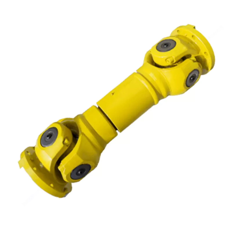
SWP-G Super Short Flexible Universal Joint Couplings
The SWP-G Super Short Flexible Universal Joint Coupling is the most compact variant in the SWP family (Lmin 435–715 mm), covering gyration diameters 225–350 mm and torques 18–71 kN·m. Its all-metal spider mechanism delivers angular compensation within a fold angle of ≤5° — ideal for food processing, chemical reactor drives, compact conveyor frames, and close-coupled pump skids where standard short-body couplings are too long to fit.
SWP-G Super Short Flexible Universal Joint Couplings — Product Overview
The SWP-G Super Short Flexible Universal Joint Coupling is the most compact member of the SWP family — designed for installations where even the short-body SWP-B or SWP-C is too long to fit. With overall installed lengths from just 435 mm (SWP225G) to 715 mm (SWP350G), the SWP-G achieves an installed footprint smaller than any other SWP variant, while retaining the core split axletree spider mechanism and telescoping sleeve that define the series.
The compactness comes with two important constraints that differentiate SWP-G from all other SWP types: fold angle is limited to ≤5° (versus ≤10° for types A–F), and the available size range covers only five diameters — D225 to D350 mm, with nominal torques from 18 to 71 kN·m. These constraints reflect the geometric reality of the super short body: shorter coupling length reduces the angular accommodation geometry, and the compact design targets the mid-range torque band where the shortest installed length is most commercially valuable.
Structural distinction — D0 centre column: The SWP-G specification includes a D0 column (centre diameter) not present in other SWP types. This dimension defines the outside diameter of the compact centre body — critical for coupling guard design in the ultra-tight installation envelopes where SWP-G is typically deployed.
Telescoping stroke: SWP-G provides Ls of 40–55 mm (D225–D350), proportional to its compact dimensions. This moderate stroke is sufficient for the assembly tolerance and thermal compensation typical in the mid-range industrial equipment where SWP-G is used.
Australian applications: Compact industrial drivetrains in food processing, chemical plant, pharmaceutical manufacturing, and light-to-medium duty material handling are increasingly demanding smaller coupling envelopes as machinery designers reduce equipment footprints. SWP-G fills a genuine gap in the Australian market for a spider-type universal joint coupling that fits where disc or jaw couplings have traditionally been used but where the angular accommodation of a Hooke's joint coupling is needed.
Critical design check — fold angle: Because SWP-G is limited to ≤5° fold angle, shaft alignment must be tighter than for SWP-A through SWP-F. Before specifying SWP-G, verify that your application's maximum shaft angular misalignment (including all sources: mounting tolerance, thermal growth, foundation settlement, shaft runout) does not exceed 5°. For applications with angular offsets between 5° and 10°, specify SWP-B as the minimum appropriate type.
Technical Specifications
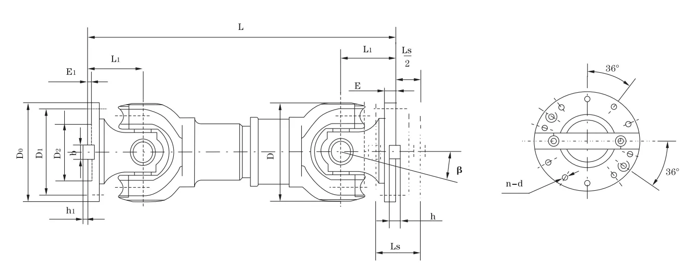
| Type | D (mm) | Tn (kN·m) | Tf (kN·m) | Ls (mm) | β | Lmin (mm) | D0 | D1 js11 | D2 H7 | E | E1 | b×h | h1 | L1 | n–d | I Lmin (kg·m²) | G Lmin (kg) |
|---|---|---|---|---|---|---|---|---|---|---|---|---|---|---|---|---|---|
| SWP225G | 225 | 18 | 8 | 40 | ≤5 | 435 | 275 | 248 | 135 | 15 | 5 | 32×18 | 9 | 68 | 10–15 | 0.331 | 60 |
| SWP250G | 250 | 25 | 11.2 | 40 | ≤5 | 515 | 305 | 275 | 150 | 15 | 5 | 40×25 | 12.5 | 80 | 10–17 | 0.624 | 97 |
| SWP285G | 285 | 35.5 | 16 | 40 | ≤5 | 565 | 348 | 314 | 170 | 18 | 7 | 40×30 | 15 | 90 | 10–19 | 1.182 | 120 |
| SWP315G | 315 | 50 | 25 | 40 | ≤5 | 620 | 360 | 328 | 185 | 18 | 7 | 40×30 | 15 | 100 | 10–19 | 2.29 | 170 |
| SWP350G | 350 | 71 | 35.5 | 55 | ≤5 | 715 | 405 | 370 | 210 | 22 | 8 | 50×32 | 16 | 108 | 10–21 | 3.793 | 256 |
Note: D=315mm, L=620mm → SWP315Gx620. SWP-G is limited to 5 sizes (D225–D350) and fold angle ≤5°. D0 = compact centre body OD (unique to SWP-G). Lmin values (435–715 mm) are the shortest in the SWP family. No ΔI/ΔG incremental columns — SWP-G is not available in extended lengths.
Industry Applications
Food Processing & Packaging Machinery Drives
Working condition: Compact machine footprint, moderate torque (18–71 kN·m covers most packaging and conveying drives), hygiene-sensitive environment requiring minimal lubricant leakage risk, frequent speed changes.
Why SWP-G: Food processing plant designers specify the smallest possible coupling envelope to maximise product flow clearance and simplify machine guarding. SWP-G's 435–715 mm overall length fits within machine bays where SWP-B would require major frame modification. The split axletree housing allows spider inspection without full drive disassembly — important in food plants where contamination risk from drivetrain disassembly must be minimised.
Customer benefit: Compact drivetrain fits existing machine bay dimensions without frame modification; minimal lubricant exposure risk with correct sealing; angular compensation tolerates modest shaft misalignment from thermal cycling of processing equipment.
Chemical & Pharmaceutical Reactor Drives
Working condition: Process equipment in restricted plant areas, moderate shaft misalignment due to reactor settlement, requirement for angular compensation without flexible element (elastomer) that could shed particles into process area.
Why SWP-G: Reactor agitator and mixer drives in chemical plants often require angular compensation but exclude elastomeric coupling elements due to particle shedding risk. SWP-G's all-metal spider mechanism provides angular compensation without elastomers. The super-short body fits within the coupling guard envelope of existing reactor drive frames.
Customer benefit: Compliant with elastomer-free process area requirements; compact body fits existing drive arrangements; spider replacement during turnarounds without frame disassembly.
Material Handling — Short Centre Distance Conveyor Drives
Working condition: Short motor-to-drive-shaft centre distances in compact conveyor frames, moderate torque, ambient dust exposure.
Why SWP-G: Compact conveyor frames in Australian warehousing and manufacturing facilities increasingly use close-coupled motor-gearbox arrangements that cannot accommodate standard short-body (SWP-B/C) coupling lengths. SWP-G's 435–715 mm Lmin covers these close-coupled arrangements without mechanical modification.
Customer benefit: Standard conveyor frame dimensions maintained; no shaft extension required; angular compensation accommodates conveyor frame flex under load.
⚙️ Light Industrial Pump & Compressor Drives
Working condition: Mid-range torque (18–71 kN·m), moderate speed, limited installation space between prime mover and pump/compressor, well-controlled shaft alignment (≤5° achievable).
Why SWP-G: Pump and compressor skid designers in Australian process industries select close-coupled arrangements to minimise skid footprint and reduce foundation requirements. SWP-G enables spider-type universal joint coupling benefits in these close-coupled skid layouts.
Customer benefit: Universal joint angular compensation in a compact skid without the footprint penalty of longer SWP types; all-metal construction compatible with process plant temperature ranges.
How to Choose: SWP-G vs SWP-B vs SWP-C
SWP-G is a highly specialised type within the SWP family. Before specifying it, two absolute requirements must be confirmed: (1) installation length is truly insufficient for SWP-B, and (2) angular misalignment does not and will not exceed 5°.
| Parameter | SWP-G (Super Short) | SWP-B (Short Flex) | SWP-C (Short Non-Flex) |
|---|---|---|---|
| Min Overall Length (D225) | 435 mm | 830 mm | 520 mm |
| Min Overall Length (D315) | 620 mm | 1120 mm | 680 mm |
| Fold Angle Limit | ≤5° | ≤10° | ≤10° |
| Axial Telescoping | ✅ Yes (40–55 mm) | ✅ Yes (50–230 mm) | ❌ None |
| Size Range | D225–D350 only | D160–D640 | D160–D640 |
| Torque Range | 18–71 kN·m | 16–1250 kN·m | 16–1250 kN·m |
| Best Use Case | Ultra-compact, ≤5° offset | Compact with moderate offset | Compact, fixed shaft, ≤10° offset |
The ≤5° Fold Angle — Practical Implications
The 5° limit of SWP-G is a hard design constraint, not a conservative guideline. Exceeding 5° continuous operating angle causes accelerated spider bearing wear and introduces a cyclic speed variation (velocity non-uniformity) in the output shaft that increases with fold angle. At 5° the non-uniformity is approximately 0.8% — acceptable for most industrial applications. At 10°, it rises to approximately 3%, which may be problematic for sensitive processes. For SWP-G applications, design the installation to operate at ≤3° continuous, reserving the 5° capacity for transient events.
⚠️ Critical Errors When Specifying SWP-G
- Exceeding the 5° fold angle limit: SWP-G rated at ≤5° — it is not interchangeable with SWP-B in applications where shaft misalignment reaches 6–10°. Overshooting the fold angle limit on SWP-G causes rapid spider cross failure and potentially damages connected equipment through excessive velocity variation.
- Specifying SWP-G for torque requirements above 71 kN·m: SWP350G has the highest torque capacity at 71 kN·m nominal (35.5 kN·m fatigue). For higher torques in a compact envelope, SWP-B is required — even if the installation space is tight, the only solution is modifying the frame to accommodate SWP-B's minimum length.
- Assuming SWP-G is a smaller SWP-B: SWP-G uses different internal geometry and a different centre body design (D0 column). It is not a scaled-down SWP-B — the two types are not interchangeable and the selection criteria are distinct.
Is SWP-G the right fit for your compact drive application? Contact Our Engineers — share your available installation length and angular misalignment data and we will confirm whether SWP-G or another type is appropriate.
Why Choose GBC for SWP-G Supply
We manufacture SWP-G to the same JB/T 3241-91 standard as the full SWP family, with specific attention to the compact centre body geometry that defines this type's unique characteristics.
Compact Precision Engineering
The SWP-G centre body (D0) is machined to tighter straightness and runout tolerances than longer SWP types, because any body bow directly impacts the coupling's velocity transmission quality at the 5° fold angle operating point. Centre bodies are ground-finished and dynamically balanced as sub-assemblies before final assembly and test.
⚖️ Balance to G6.3
All SWP-G assemblies are dynamically balanced to ISO 1940 G6.3 as standard — the same balance grade as larger SWP types, which is more demanding at the shorter body lengths of SWP-G. For food processing and pharmaceutical applications requiring G2.5 balance, we offer this as an upgrade option. Balance report issued with each coupling.
Material Specifications
Yokes: 42CrMo4 alloy steel, quench-tempered. Spider crosses: 20CrMnTi, case-hardened 58–62 HRC. Centre body: seamless 45# steel tube, normalised. Flange faces: ground to Ra ≤1.6 μm. Standard surface treatment: manganese phosphate + oil. Optional: zinc plating or stainless fasteners for washdown environments.
Stock & Lead Time
SWP-G is available in all five standard sizes (D225–D350) with semi-finished yoke stock maintained for rapid assembly. Standard lead time: 10–15 business days. Given the limited size range and relatively lower weight of SWP-G, air freight to Australia is commercially practical for small quantities — typical delivery to Australian capitals within 12–18 business days including production and transit.
Customer Reviews & Case Studies
Australia — Food Processing Line Drive, Victoria
★★★★★
We needed a compact coupling for a new conveyor drive in our food processing line. Our frame allowed a maximum coupling length of 580 mm — SWP-B was 540 mm too long for our frame at D250. SWP250G at 515 mm fit perfectly. The split housing made our first 6-month inspection straightforward. Great product for a tight space.
— Mechanical Engineer, Victorian Food Processing Facility
Germany — Chemical Reactor Agitator Drive, Rhine Valley
★★★★★
We replaced elastomeric jaw couplings on our reactor agitator drives with SWP285G units after recurring elastomer particle contamination events. The all-metal spider type eliminates the contamination risk completely. The 5° fold angle limit was not an issue — our alignment is held to ±1.5°. Twelve months of operation, zero contamination incidents.
— Process Engineer, German Chemical Plant
Singapore — Compact Pump Skid Drive
★★★★☆
SWP315G specified for a close-coupled pump skid in a refinery unit. The 620 mm overall length fit our skid design with 8 mm clearance to the guard — very tight but it worked. Coupling has been in service for 10 months with no maintenance required. Slightly concerned about the tight clearance but the coupling has not moved outside spec.
— Skid Design Engineer, Singapore Industrial Equipment Supplier
Italy — Packaging Machinery Drive, Emilia-Romagna
★★★★★
We tested GBC SWP-G against our incumbent Italian coupling supplier for our new packaging machine line. GBC quality was equivalent, dimensional accuracy identical, and price 18% lower. We qualified GBC as our standard supplier for this component across the product line. Deliveries have been consistent and on-time for eight orders.
— Purchasing Director, Italian Packaging Machinery Manufacturer
Frequently Asked Questions
Why is SWP-G limited to only 5 sizes (D225–D350) while other SWP types cover D160–D640?
The SWP-G size range is limited to D225–D350 in the JB/T 3241-91 standard because the super short body design is most commercially and technically viable in this mid-range torque band (18–71 kN·m). At smaller diameters (D160–D200), the overall length reduction versus SWP-B becomes very small and the engineering benefit diminishes. At larger diameters (D390+), the physical length of the double Hooke's joint assembly cannot be reduced sufficiently to qualify as "super short" without compromising the fold angle further below the 5° minimum practical limit. For applications below D225 or above D350 requiring compact coupling, consider SWP-B (short flex) as the closest alternative.
Can SWP-G be used as a direct replacement for a jaw or disc coupling?
SWP-G can replace jaw or disc couplings in applications where: (1) the shaft misalignment is within ≤5° angular; (2) torque is within 18–71 kN·m (SWP225G–SWP350G); (3) the installation length accommodates SWP-G Lmin (435–715 mm). The primary advantage of upgrading from jaw/disc to SWP-G is the higher angular capacity (jaw couplings typically ≤1°; disc couplings typically ≤0.5°) and the in-situ maintainability of the split axletree housing. Bore dimensions and flange interfaces will typically require adaptation when replacing jaw or disc couplings — provide your existing coupling dimensions for a compatibility assessment.
What alignment precision is required for SWP-G installation?
SWP-G requires more precise shaft alignment than longer SWP types due to its ≤5° fold angle limit. Installation alignment target: angular misalignment ≤3° (to preserve margin below the 5° limit for operational movement), parallel offset ≤1 mm (which contributes to effective fold angle). Laser alignment is strongly recommended — dial indicator alignment is acceptable but less accurate at these tight tolerances. After alignment, verify that thermal growth and dynamic loads during operation do not bring the fold angle above 5°. For food processing and chemical plant installations where thermal growth from startup is significant, perform a hot alignment check and correct if necessary.
What is the difference between SWP-G and SWP-B in terms of velocity transmission quality?
Both types use the Hooke's joint (universal joint) mechanism, which inherently produces a cyclic variation in output shaft angular velocity relative to input when operated at a fold angle. The velocity non-uniformity factor u = (cos β × sin²β) / (1 - cos²β × sin²φ), where β is fold angle and φ is rotation angle. At the SWP-G design limit of 5°, the peak velocity variation is approximately ±0.8% per joint. For SWP-B at its 10° limit, it is approximately ±3%. SWP-G operated within 3° continuous is essentially equivalent to a constant-velocity joint for all practical industrial purposes. The critical difference is that SWP-G's compact body magnifies the effect of any misalignment — staying well within the 5° limit matters more for SWP-G than for longer types.
Is there a high-speed version of SWP-G available?
The standard SWP-G is dynamically balanced to ISO 1940 G6.3, which supports operating speeds up to approximately: D225G ≤2000 rpm; D250G ≤1800 rpm; D285G ≤1500 rpm; D315G ≤1200 rpm; D350G ≤1000 rpm. For higher-speed applications, we can supply G2.5 precision balance on request, extending the practical speed range by approximately 25–30% per step. For drives above 2500 rpm at D225–D250, a critical speed calculation is recommended before ordering. Provide your operating speed, fold angle, and installation length for a speed capability assessment.
Enquire About SWP-G Super Short Couplings
Compact Drive Application? SWP-G Is Ready to Fit
When installation space is the primary design constraint and standard short-body couplings won't fit, SWP-G delivers spider-type universal joint performance in the most compact envelope in the SWP range. Share your available length, torque, and alignment data — we'll confirm suitability and quote within one business day.
Check Fit for My Application
Request a Sample / Prototype
ISO 9001:2015 · Compact Industrial Coupling Specialists · Air & Sea Freight to Australia
The SWP-G Super Short Flexible Universal Joint Coupling is the most compact variant in the SWP family (Lmin 435–715 mm), covering gyration diameters 225–350 mm and torques 18–71 kN·m. Its all-metal spider mechanism delivers angular compensation within a fold angle of ≤5° — ideal for food processing, chemical reactor drives, compact conveyor frames, and close-coupled pump skids where standard short-body couplings are too long to fit.
Related products
-
DJM Type Single Flexible Diaphragm Coupling
-
SWP-D Long Non-Flexible Universal Joint Couplings
-
SWP-A Long Flexible Universal Joint Couplings
-
WGC Vertical Installation Drum Shape Gear Coupling
-
ML Plum Blossom Type Elastic Shaft Coupling
-
NGCLZ Drum Shape Gear Coupling with Brake Drum | Intermediate Shaft Type