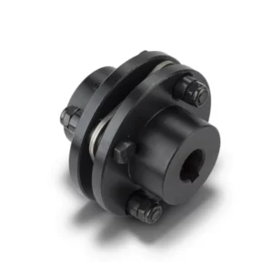
WG Drum Shape Gear Coupling
Crowned-tooth gear coupling with built-in lubrication port per JB/T8854.2. Type I (WG1–WG24) and Type II (WG1–WG14). 710 N·m to 1,250,000 N·m, up to 7500 RPM. Y/J1/Z1 bores. Foundation of WGP/WGC/WGZ/WGT family. Factory direct to Australia.
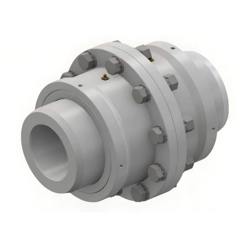
WG Drum Shape Gear Coupling — Type I & Type II
High-rigidity, compact crowned-tooth gear coupling with built-in lubrication port. The foundation of the WG family — 24 sizes, two construction types, massive torque range, and Z1 taper bore option. Factory direct to Australia.
Product Overview
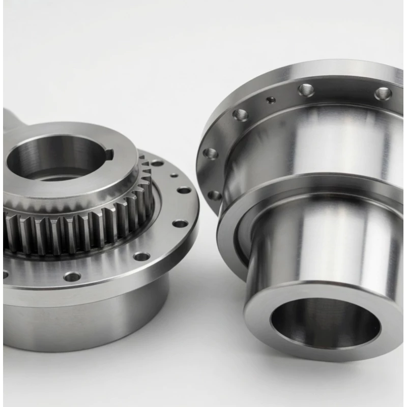
The WG drum shape gear coupling is a heavy-duty, high-rigidity crowned-tooth gear coupling built for the most demanding horizontal shaft drive applications in mining, steel, power generation, cement, and general heavy industry. It is the base model of the broader WG coupling family — a versatile platform that extends into brake disc (WGP), vertical installation (WGC), brake drum (WGZ), and intermediate sleeve (WGT) variants, all sharing the same crowned gear mesh technology at their core.
What sets the WG apart from other drum shape gear coupling series is its combination of two distinct construction types, a wide 24-size range spanning three orders of magnitude in torque capacity, and a built-in lubrication port that simplifies maintenance access. The Type I design (WG1–WG24) uses a single outer sleeve and suits the majority of horizontal drive train applications. The Type II design (WG1–WG14) adds an inner bore collar for improved hub engagement, suited to higher shock load duty cycles and more demanding industrial environments.
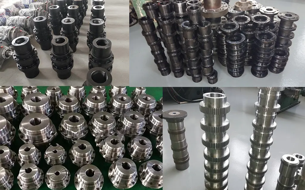
At GBC, we manufacture and export WG couplings factory-direct to Australian customers across mining, processing, water infrastructure, and industrial manufacturing. Every coupling ships with full material traceability, dimensional inspection records, and ISPM-15 compliant packing.
Technical Definition and Working Principle
What Makes the WG a Drum Shape Coupling
The WG is a moveable rigid coupling that transmits torque through two crowned (barrel-shaped) gear meshes — one on each side of the coupling. Each coupling half consists of a hub with external crowned teeth that mesh with internal straight teeth inside a common outer sleeve. The two-mesh design provides angular, radial, and axial misalignment compensation simultaneously at each tooth interface.
The crown radius machined into each external tooth profile is the defining technical feature that distinguishes the WG from a straight-tooth gear coupling. In a straight-tooth design, torque is transmitted through a full-face line contact that concentrates at the tooth edges under any shaft misalignment — generating destructive edge loading stresses. The WG's crowned profile creates a self-centering Hertzian contact ellipse that remains near the tooth centre regardless of the misalignment angle, distributing contact stress uniformly and eliminating edge loading entirely.
The WG's built-in lubrication port on the outer sleeve is a practical engineering detail that separates it from couplings requiring partial disassembly for lubrication. Grease or oil is injected directly through the port into the tooth mesh space, making re-lubrication a scheduled maintenance task rather than a coupling replacement trigger.
Type I vs Type II Construction
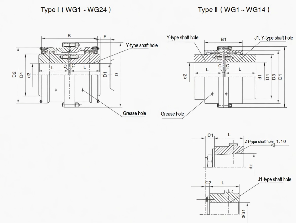
The WG is offered in two structural variants for WG1 through WG14:
- Type I (WG1–WG24): Standard single outer sleeve configuration. The outer sleeve spans both hubs continuously, providing a compact overall length B. This is the most widely used configuration for standard horizontal industrial drives.
- Type II (WG1–WG14): Features a split or flanged sleeve arrangement with an additional B1 hub engagement length. The Type II provides greater axial retention of each hub within the sleeve and is preferred in applications with frequent torque reversals, higher vibration, or elevated shock loading where the additional B1 engagement reduces the risk of hub axial displacement.
For WG15 through WG24 — the largest sizes in the series — only Type I is available, as the outer dimensions of these sizes make the Type II split construction impractical. These large sizes serve the heaviest industrial drives: steel mill main drives, large conveyor systems, and heavy crusher drives.
Comparison with Other Coupling Types
| Feature | WG (this product) | Jaw Coupling | Disc Coupling | Rigid Flange |
|---|---|---|---|---|
| Torque Range | 0.71–1250 KN·m | Low–Medium | Medium | High |
| Angular Misalignment | 1.0–1.5 deg per mesh | Up to 1 deg | Up to 1 deg | Near zero |
| Shock Load Tolerance | Excellent | Good (elastomer) | Poor | Transmitted fully |
| Z1 Taper Bore | Yes — standard option | Limited | No | No |
| Built-in Lubrication Port | Yes — standard | No (no lube) | No | No |
| Axial Displacement | Yes (built-in) | Limited | Yes | No |
| Two Construction Types | Yes — Type I & Type II | No | No | No |
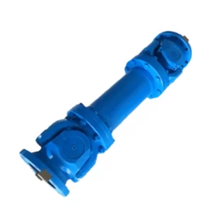
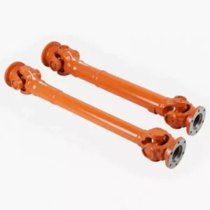
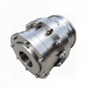
WG vs WGP vs WGC vs WGZ vs WGT — Which Variant Is Right for You?
All five variants share the WG crowned gear mesh as their core transmission element. The choice between them depends on your application's braking requirements, shaft orientation, and shaft spacing. The table below clarifies the key differences:
| Feature | WG | WGP | WGC | WGZ | WGT |
|---|---|---|---|---|---|
| Full Name | Standard drum gear coupling | With brake disc (flat disc) | Vertical installation type | With brake drum (cylindrical) | With intermediate sleeve (spacer) |
| Standard | JB/T8854.2 / JB/ZQ4186 | JB/T7001 | JB/T7002-93 | JB/T7003-93 | JB/T7004 |
| Braking Feature | None | Flat brake disc for caliper brakes | None | Cylindrical drum for shoe brakes | None |
| Shaft Orientation | Horizontal | Horizontal | Vertical — purpose designed | Horizontal | Horizontal |
| Intermediate Shaft | No | No | No | No | Yes — for distant shafts |
| Number of Sizes | 24 (WG1–WG24) | 14 (WGP1–WGP14) | 14 (WGC1–WGC14) | 14 (WGZ1–WGZ14) | 24 (WGT1–WGT24) |
| Lubrication Port | Yes | Yes | Yes | Yes | Yes |
| Choose When... | Standard horizontal drive, no braking needed | Caliper braking required (e.g. crane hoists, VFD drives) | Vertical shaft drive (pumps, fans, agitators) | Shoe brake system required (hoists, cranes) | Motor and gearbox are far apart, or axle withdrawal needed |
Specifications & Size Matrix — WG1 to WG24
All specifications are from the WG product catalogue per JB/T8854.2 and JB/ZQ4186. Dimensions in millimetres. Where two values appear for C and weight, the first is Type I and the second is Type II. WG15–WG24 are Type I only.
WG1 – WG12 Specifications (Type I and Type II)
| Type | Torque (N·m) |
Speed (rpm) |
Shaft Bore d1,d2,dz (mm) |
Y | J1, Z1 | D | D1 | D2 | D3 | D4 | B | B1 | F | Inertia I (Kg·m²) |
Inertia II (Kg·m²) |
Weight I (Kg) |
Weight II (Kg) |
|---|---|---|---|---|---|---|---|---|---|---|---|---|---|---|---|---|---|
| WG1 | 710 | 7500 | 12–42 | 32–112 | –/44/84 | 122 | 115 | 98 | 88 | 60 | 116 | 100 | 30 | 0.008 | 0.0063 | 5.6 | 4.86 |
| WG2 | 1250 | 6700 | 22–56 | 52–112 | –/60/84 | 150 | 145 | 118 | 108 | 77 | 136 | 104 | 30 | 0.021 | 0.016 | 9.78 | 7.48 |
| WG3 | 2500 | 6300 | 22–63 | 52–142 | –/60/107 | 170 | 165 | 140 | 125 | 90 | 160 | 108 | 30 | 0.047 | 0.033 | 16.7 | 12.2 |
| WG4 | 4500 | 5600 | 30–80 | 82–172 | –/84/132 | 200 | 195 | 160 | 145 | 112 | 180 | 116 | 30 | 0.098 | 0.073 | 25.6 | 19.6 |
| WG5 | 7100 | 5300 | 30–90 | 82–172 | –/84/132 | 225 | 215 | 180 | 168 | 128 | 200 | 126 | 30 | 0.175 | 0.126 | 35 | 26.1 |
| WG6 | 10000 | 5000 | 32–100 | 82–212 | –/107/167 | 245 | 230 | 200 | 185 | 145 | 224 | 134 | 30 | 0.295 | 0.213 | 51.6 | 38 |
| WG7 | 14000 | 4500 | 32–110 | 82–212 | –/107/167 | 272 | 265 | 230 | 210 | 160 | 244 | 148 | 30 | 0.53 | 0.35 | 68.6 | 45 |
| WG8 | 20000 | 4250 | 55–125 | 112–212 | –/107/167 | 290 | 272 | 245 | 225 | 176 | 272 | 162 | 30 | 0.71 | 0.46 | 79.5 | 55.8 |
| WG9 | 25000 | 4000 | 65–140 | 142–252 | 107/202 | 315 | 305 | 265 | 245 | 190 | 280 | 176 | 30 | 1.05 | 0.77 | 106.5 | 80.5 |
| WG10 | 40000 | 3550 | 75–160 | 142–302 | 107/242 | 355 | 340 | 300 | 280 | 225 | 330 | 196 | 30 | 1.87 | 1.54 | 158.8 | 121.8 |
| WG11 | 56000 | 3000 | 85–180 | 172–302 | 132/242 | 412 | 385 | 345 | 325 | 256 | 360 | 224 | 40 | 3.66 | 2.77 | 214 | 167 |
| WG12 | 80000 | 2800 | 120–200 | 212–352 | 167/282 | 440 | 435 | 375 | 360 | 288 | 414 | 250 | 40 | 6.39 | 4.75 | 302 | 142 |
WG13 – WG24 Specifications (Type I Only)
| Type | Torque (N·m) |
Speed (rpm) |
Bore Range (mm) |
Y Range | D | D2 | D4 | B | F | Inertia I (Kg·m²) |
Weight I (Kg) |
|---|---|---|---|---|---|---|---|---|---|---|---|
| WG13 | 112000 | 2500 | 140–220 | 252–352 | 490 | 425 | 320 | 470 | 50 | 10.44 | 390 |
| WG14 | 160000 | 2300 | 160–260 | 302–410 | 545 | 462 | 362 | 530 | 50 | 17.46 | 522 |
| WG15 | 224000 | 2100 | 160–270 | 302–470 | 580 | 488 | 400 | 560 | 50 | 24.91 | 677 |
| WG16 | 280000 | 1900 | 180–300 | 302–470 | 650 | 560 | 440 | 600 | 50 | 43.22 | 939 |
| WG17 | 355000 | 1800 | 200–320 | 352–470 | 690 | 600 | 460 | 650 | 50 | 56.27 | 1041 |
| WG18 | 450000 | 1700 | 220–360 | 352–550 | 750 | 650 | 510 | 700 | 60 | 88.17 | 1381 |
| WG19 | 560000 | 1600 | 240–380 | 410–550 | 775 | 690 | 535 | 745 | 60 | 108.8 | 1526 |
| WG20 | 710000 | 1500 | 260–400 | 410–650 | 825 | 730 | 580 | 785 | 60 | 164.4 | 2081 |
| WG21 | 800000 | 1300 | 280–440 | 470–650 | 925 | 825 | 620 | 810 | 60 | 242.7 | 2460 |
| WG22 | 900000 | 950 | 320–460 | 470–650 | 950 | 850 | 665 | 820 | 60 | 297 | 2775 |
| WG23 | 1000000 | 900 | 360–500 | 550–650 | 1030 | 900 | 710 | 880 | 60 | 384.8 | 3148 |
| WG24 | 1250000 | 850 | 380–520 | 550–800 | 1060 | 925 | 730 | 900 | 70 | 477.8 | 3766 |
Note: Torque values are in N·m (divide by 1000 for KN·m). Y column shows the bore length range for Y type shaft holes. J1/Z1 bore lengths are longer — refer to catalogue table C1/C2 values. Type II data not available for WG13–WG24 (Type I only).
Custom Bore, Type Selection & Shaft Fit Available
Need a specific Y, J1, or Z1 bore diameter not listed in the standard range, a custom keyway, or Type II construction for a larger size? Our engineering team evaluates custom requests and provides solutions within 5–10 working days. Send your shaft drawing here.
Industries & Applications in Australia
The WG drum shape gear coupling serves as the standard horizontal shaft coupling across Australia's heaviest industrial sectors. Its wide size range — from compact WG1 units in small conveyor drives to 3.7-tonne WG24 couplings in steel mill main drives — means a single coupling family covers virtually every horizontal power transmission requirement in Australian industry.
Mining — Conveyors, Crushers, and Mill Drives
Equipment: Belt conveyor head drives, overland conveyor drives, primary and secondary crusher drives, ball mills, SAG mills, scrubbers.
In Australian iron ore, coal, and gold operations, WG couplings from WG8 through WG20 serve the majority of conveyor and crusher drive applications. The built-in lubrication port is a major practical advantage on conveyor head drives in remote Pilbara and Hunter Valley locations, where re-lubrication without disassembly saves hours of maintenance time per interval. The Type II construction of WG8–WG12 is preferred on crusher drives where torque reversals occur during material blockage clearance.
Steel Manufacturing
Equipment: Rolling mill main drives, roughing and finishing mill stands, continuous caster drives, coiler and uncoiler drives, shear drives.
The largest WG sizes — WG18 through WG24 — are purpose-designed for the main drives of heavy rolling mills. At 450,000 to 1,250,000 N·m rated torque, these couplings handle the full transmitted load of steel mill main drives while accommodating the angular misalignment caused by thermal distortion of mill housing foundations during extended campaign runs. The steel body of the WG handles mill-side shock loading from each rolling pass without the fatigue failures that rigid couplings exhibit in the same service. Learn more about our full range of industrial couplings.
Pump and Compressor Drives
Equipment: Centrifugal pump drives, multi-stage pump drives, screw compressor drives, reciprocating compressor drives, blower drives.
Water utilities across Sydney, Melbourne, Brisbane, Perth, and Adelaide rely on WG couplings in their major pumping stations. The WG's axial displacement capability absorbs thermal growth in motor and pump shafts during extended continuous operation, preventing axial thrust from loading motor bearings — a common failure mode when rigid couplings are used on large centrifugal pump drives. The Z1 taper bore option is valued by Australian pump OEMs for IEC motor connections where keyless fits are preferred.
Cement and Building Materials
Equipment: Rotary kiln drives, raw mill drives, cement mill drives, vertical roller mill drives, clinker cooler drives.
Cement plants in Queensland, South Australia, and Western Australia operate some of the most torque-intensive drives in Australian industry. WG14 to WG19 couplings handle kiln and mill main drive torques from 160,000 to 560,000 N·m. The WG's tolerance of thermally-induced axial displacement is essential on rotary kiln drives, where kiln shell thermal expansion pushes the drive shaft axially throughout each operating cycle.
Power Generation and Fan Drives
Equipment: Turbine auxiliary drives, boiler feed pump drives, induced draft fan drives, forced draft fan drives, coal pulveriser drives.
Power stations in the Hunter Valley, Latrobe Valley, and Queensland rely on WG couplings in their auxiliary drive trains. The WG's high-speed capability (up to 7500 RPM for WG1) and two-mesh crowned tooth design make it suitable for both low-speed, high-torque drives like ID fans and medium-speed pump drives. The lubrication port simplifies in-situ maintenance on power station drives where coupling access is often constrained by ductwork and structural steelwork.
Technical Advantages — Why Crowned Tooth Outperforms Straight Tooth
Higher Misalignment Tolerance — Critical for Australian Mining Sites
Australian mine conveyor drives on expansive soils in the Pilbara and Hunter Valley can experience foundation settlement of several millimetres per year, causing progressive shaft misalignment. The WG's crowned tooth profile accommodates 1.0–1.5 degrees of angular misalignment per mesh continuously without any increase in tooth contact stress — compared to the 0.3–0.5 degree limit of straight-tooth couplings before destructive edge loading begins. In documented conveyor drive comparisons on Australian iron ore sites, WG-type crowned couplings achieve 3–5 years of service life against 6–12 months for straight-tooth equivalents in the same misalignment conditions.
Longer Service Life Under Shock Loads
Crusher and mill drives experience torsional shock peaks of 2–4x nominal torque during material ingestion and blockage events. The WG's crowned tooth distributes these peak loads as a Hertzian contact ellipse, significantly reducing maximum surface stress compared to the line contact of a straight-tooth coupling under the same peak torque. In Australian hard rock crusher applications, WG-type crowned couplings typically deliver 2–4x longer tooth life versus straight-tooth equivalents, with a corresponding reduction in unplanned coupling replacement downtime.
Reduced Bearing Loads
A misaligned straight-tooth coupling generates cyclic bending moments at 2x running frequency, loading motor and gearbox bearings with parasitic radial forces that accelerate bearing fatigue. The WG's self-centering crowned teeth minimise these misalignment-induced forces, protecting adjacent bearings from over-loading. Australian industry case data consistently shows 30–50% reductions in motor drive-end bearing replacement frequency after replacing straight-tooth couplings with WG-type crowned units in otherwise identical applications.
Lower Maintenance Frequency — With Built-In Lubrication Port
The WG's lubrication port is more than a convenience — it fundamentally changes the maintenance workflow. Re-lubrication requires only the injection of fresh grease through the port with the coupling running or briefly stopped, without any disassembly. Standard intervals are 6–12 months under normal conditions. On remote Australian mine sites where maintenance events require fly-in crews and permit-to-work procedures, halving the lubrication frequency versus competing designs saves measurable operational cost per coupling per year.
Suitable for High-Speed Applications
WG1 is rated to 7500 RPM — the highest speed in the drum shape gear coupling family — making it suitable for direct 2-pole motor coupling on 50 Hz supplies. The crowned tooth profile generates significantly less vibration excitation at speed than straight-tooth equivalents under misalignment, keeping vibration within acceptable limits for motor warranty compliance. For VSD-driven drives, the WG remains dynamically stable across the full speed range from zero to maximum without requiring rebalancing.
Manufacturing & Quality Assurance
Manufacturing Process
WG couplings are manufactured from forged alloy steel blanks — 42CrMo4 for WG8 and above, 45# carbon steel for smaller sizes. The crowned external tooth profiles are CNC hobbed to DIN Class 7 accuracy using dedicated crowned-tooth tooling. Tooth flanks are carburised and quenched to HRC 58–62 surface hardness with HRC 30–35 core hardness. The outer sleeve internal straight teeth are broached or hobbed to the same DIN Class 7 standard, ensuring correct mesh contact across the full tooth width.
The lubrication port is drilled and tapped after all machining is complete, with thread-form verified for compatibility with standard grease nipple specifications. All bores are finish-machined to H7 tolerance. Z1 conical bores are verified with taper gauges and blue-contact checks to ensure minimum 70% taper contact for secure shaft engagement.
Quality Control Flow
Certifications
ISO 9001:2015 quality management certification covers all WG manufacturing operations from raw material receipt through to finished goods dispatch. CE marking applies to applicable sizes. Products manufactured per JB/T8854.2 and JB/ZQ4186 standards. Every shipment includes material mill certificates, heat treatment records, dimensional inspection reports, and hardness test certificates.
Why Source Your WG Couplings from GBC?
Australian Standards and Operating Conditions
We understand the operating conditions specific to Australian industry — extreme temperatures, high dust environments, remote site access constraints, and the demanding duty cycles of Australian mining and processing plants. Our coupling specifications and material selections reflect these conditions rather than generic catalogue standards.
15+ Years of Australian Export Experience
GBC has exported WG and WG-family couplings to Australian customers since 2010. We have delivered to mine sites in WA and QLD, steel mills in NSW and SA, and cement plants across every state. Our ISPM-15 packing and AQIS compliance record is clean across 15 years of Australian exports.
English-Speaking Engineering Team
Our engineers communicate in technical English, review drive train drawings, confirm coupling size selection, and validate bore and keyway specifications against customer shaft data sheets. We support the full selection workflow — from torque calculation to finished coupling specification — without language barriers or terminology confusion.
Flexible MOQ from Single Units
WG couplings are available from a single piece. Australian maintenance teams replacing a single failed coupling on short notice are as welcome as large project orders. Standard sizes ship within 15–20 working days ex-works; custom bore configurations add 5–10 working days. Bulk pricing applies for orders of 5 or more identical units.
Full WG Family — One Supplier
As the manufacturer of the complete WG family — WG, WGP, WGC, WGZ, and WGT — GBC can supply all variants from a single source. If your project requires WG couplings for standard drives and WGT for distant-shaft applications on the same site, you deal with one engineering team, one procurement process, and one documentation package. Contact us to discuss your project requirements.
Factory Direct — Full Traceability
GBC is the manufacturer. Every WG coupling ships with heat number-traceable material certificates, heat treatment records, and hardness reports. Australian buyers switching from third-party resellers consistently achieve 20–35% cost reductions when ordering factory-direct while receiving the same or better documentation quality.
Application Case Studies
Case 1: Iron Ore Conveyor Drive Standardisation — Pilbara, WA
Customer Profile: A large iron ore producer operating a 47 km overland conveyor system in the Pilbara, with 12 drive stations using various coupling brands and types accumulated over 15 years of piecemeal maintenance.
Challenge: The mixed coupling inventory was creating a spares management problem — different coupling brands required different lubricants, different re-lubrication tools, and different maintenance procedures. Annual coupling failures across the fleet averaged 8–10 per year. Three couplings still used straight-tooth designs that were failing every 8–12 months due to foundation settlement misalignment.
Solution: We supplied 12x WG10 couplings (40,000 N·m, 150 mm bore, Type I) across all 12 drive stations, standardising the entire fleet to a single coupling family with identical maintenance procedures and lubricant specification. The three previously straight-tooth stations received WG10 Type II for additional shock resistance.
Result: In the 30 months since standardisation, total coupling failures across all 12 drives dropped from an average of 8–10 per year to zero. The maintenance team reduced coupling-related spares inventory value by 62% through the rationalisation. Annual re-lubrication cost across the fleet reduced by 35% due to the longer interval and single-tool access via the WG port.
Case 2: Cement Mill Main Drive — Queensland
Customer Profile: A cement manufacturer in South East Queensland operating a 3.5 m diameter ball mill with a 2250 kW main drive.
Challenge: The existing coupling on the mill main drive was a disc-pack type that had failed three times in 18 months due to disc fatigue from combined angular and axial misalignment caused by kiln thermal growth. Each failure required a 48-hour planned replacement outage. The plant's engineering team assessed that 0.7 degrees of persistent angular misalignment was beyond the disc coupling's rated tolerance.
Solution: We supplied a WG15 coupling (224,000 N·m, 240 mm bore, Type I). The WG15's crowned tooth profile handles the 0.7 degree misalignment continuously without stress concentration — well within its 1.0–1.5 degree tolerance — and the axial sliding capability absorbs the kiln thermal growth that was loading the previous disc pack.
Result: The WG15 has operated for 26 months without failure or intervention beyond scheduled lubrication. The estimated saving from three avoided replacement outages (3 x 48 hours at estimated AUD $35,000 per outage in production loss) exceeds AUD $100,000 over the period.
Case 3: Steel Rolling Mill Upgrade — NSW
Customer Profile: An integrated steel mill in NSW performing a major refurbishment of the 5-stand hot strip rolling mill, requiring new couplings on all stands.
Challenge: The existing couplings on stands 3–5 were straight-tooth gear couplings experiencing tooth spalling every 6–8 months due to the severe torque reversals from the rolling pass cycle. The customer's engineering team required a complete coupling replacement with a 3-year minimum service life target and a maximum 2-week delivery lead time for planned outage scheduling.
Solution: We supplied 6x WG17 couplings (355,000 N·m, 280 mm bore, Type I) — one driving and one non-driving for each of the three stands — with custom keyways per the customer's spindle drawing. Emergency stocking from our finished goods inventory reduced ex-works lead time to 8 working days.
Result: All six WG17 couplings completed 28 months of continuous production without tooth failure or unplanned replacement. The 3-year service life target was met with margin. The mill's maintenance manager extended the lubrication interval from 4 months (used on the previous straight-tooth units) to 10 months on the WG17 units, saving approximately AUD $18,000 per year in maintenance labour across the three stands.
Frequently Asked Questions
What is a WG drum shape gear coupling?
The WG is a high-rigidity, compact crowned-tooth gear coupling with a built-in lubrication port. It is available in Type I (WG1–WG24) and Type II (WG1–WG14), covering 24 sizes from 710 N·m (0.71 KN·m) to 1,250,000 N·m (1250 KN·m) and up to 7500 RPM. It supports Y, J1, and Z1 shaft bores and is the foundational model of the WG coupling family including WGP, WGC, WGZ, and WGT variants.
What is the difference between WG Type I and Type II?
Both Type I and II share the same outer diameter, torque rating, and shaft bore options. Type I has a single continuous outer sleeve (B dimension). Type II adds an inner bore collar with longer hub engagement (B1 dimension), providing greater axial retention and better performance under torque reversals and shock loads. Type II is available for WG1–WG14; WG15–WG24 are Type I only.
How does the WG lubrication port work?
The WG has a standard grease nipple port on the outer sleeve that allows EP-grade grease or gear oil injection directly into the tooth mesh space without disassembly. Re-lubrication can be performed with the coupling running or briefly stopped, using a standard grease gun. Standard intervals are 6–12 months under normal conditions. The port location and nipple thread specification are consistent across all WG sizes for standardised maintenance tooling.
What is the difference between WG and GIICLZ couplings?
Both are crowned-tooth gear couplings. The WG has an integral lubrication port and two construction types (I and II); it is the base of the WG family including brake and vertical variants. The GIICLZ is an intermediate-shaft (spacer) type without a lubrication port, designed specifically for connecting widely separated shafts. The WG covers a broader torque range (up to 1250 KN·m vs GIICLZ's 4500 KN·m maximum, but starts from a lower 0.71 KN·m). For standard horizontal shaft connections explore our complete couplings range.
Can I get a WGP, WGC, WGZ, or WGT in the same sizes as WG?
WGP, WGC, WGZ, and WGT share many sizes with the WG base series but have size-specific limits. WGP, WGC, and WGZ are available up to 14 sizes due to the additional brake or vertical installation components. WGT (intermediate sleeve) matches the WG in offering 24 sizes. Contact our engineering team with your application requirements and we will recommend the appropriate WG family variant and size combination.
What is the angular misalignment tolerance of the WG coupling?
The WG accommodates angular misalignment of 1.0 to 1.5 degrees per tooth mesh. With two meshes in the WG design, the total system can tolerate up to approximately 3 degrees of combined angular offset between the two shaft ends. Radial (parallel) misalignment tolerance depends on the coupling size. Axial displacement is built-in through the axial sliding capability of the crowned teeth within the outer sleeve. For specific misalignment tolerance data for your required WG size, contact our engineering team.
Get Your WG Coupling Specified and Quoted
Send us your torque requirement, shaft dimensions, required construction type (I or II), and application details. Our engineering team confirms the right WG size and provides a competitive factory-direct quotation within 24 hours.
|
English-speaking engineering team
|
sales@australia-drive.com
GBC — Factory-direct WG drum shape gear couplings for Australian industry since 2010.
Crowned-tooth gear coupling with built-in lubrication port per JB/T8854.2. Type I (WG1–WG24) and Type II (WG1–WG14). 710 N·m to 1,250,000 N·m, up to 7500 RPM. Y/J1/Z1 bores. Foundation of WGP/WGC/WGZ/WGT family. Factory direct to Australia.