JSD Single Flange Grid Coupling
The JSD Single Flange Grid Coupling features one flanged hub and one keyed shaft hub, bridging flange-connected and shaft-mounted equipment. With 19 sizes from 45 to 160,000 N·m, it provides the flexibility needed for mixed-interface drive trains in power generation, steel production, and heavy process machinery.
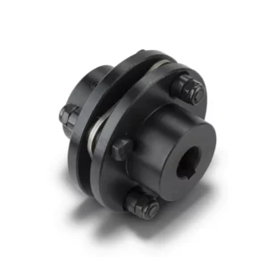
JSD Single Flange Grid Coupling – Hybrid Flange-to-Shaft Serpentine Spring Coupling
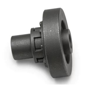
The JSD Single Flange Grid Coupling is a hybrid connection solution that pairs one flanged hub (connecting flange d1) with one standard keyed shaft hub (half-shaft coupling d). This asymmetric design addresses a common industrial scenario: connecting a flanged output – such as a gearbox or turbine flange – to a cylindrical keyed shaft on a motor, pump, or generator.
Spanning 19 models from JSD1 (45 N·m) to JSD19 (160,000 N·m), the coupling retains the serpentine spring core technology with 36% vibration damping, 99.47% transmission efficiency, and 2x overload tolerance. The single flange design is lighter and more compact than the double flange JSS variant, making it the economical choice when only one equipment interface requires a flanged connection.
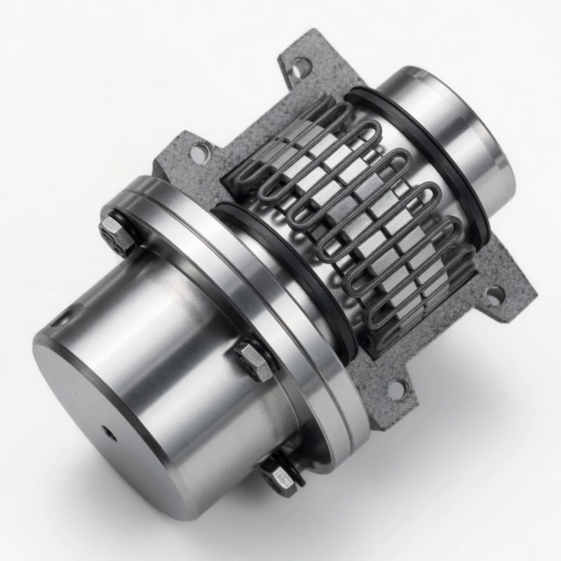
Fig. 1 – JSD Single Flange Grid Coupling product assembly
Engineering Advantages of the Single Flange Design
Mixed Interface Compatibility
One flange end connects to bolted equipment interfaces (gearboxes, turbines, generators), while the keyed shaft end mounts directly on a cylindrical shaft – bridging two different coupling philosophies in a single unit.
Reduced Weight vs. Double Flange
By replacing one flanged hub with a standard keyed hub, the JSD saves 15–30% weight compared to the equivalent JSS model, reducing bearing loads and foundation requirements.
Variable Shaft Gap (L2)
Each model specifies minimum and maximum L2 distances between the flange face and shaft hub face, accommodating different equipment spacings during installation.
Dual Bore Specifications
The flange side (d1) and shaft side (d) each support independent bore diameter ranges, allowing engineers to match different shaft sizes on driving and driven equipment.
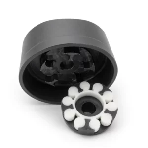
Serpentine Spring Damping
The same premium spring steel element used across all grid coupling variants absorbs torsional oscillations, protecting both the flanged and shaft-mounted equipment from resonance damage.
Field-Replaceable Spring
Spring replacement requires only shell removal – no need to disconnect the flange bolts or withdraw the shaft hub from its keyed connection.
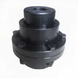
Structural Configuration
The JSD coupling combines elements of both the JS standard and JSS double flange designs:
Flange Hub (Connecting Flange d1): One hub integrates a precision-drilled connecting flange with bolt circle matching the driven equipment. Available flange bores are listed separately from the shaft-side bores.
Shaft Hub (Half-Shaft Coupling d): The opposite hub is a standard keyed-bore hub identical to those used in JS and JSB couplings. This provides a familiar and proven shaft-mounting interface.
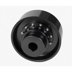
Serpentine Spring & Shell: The spring and enclosing shell are functionally identical to other grid coupling variants. Two shell configurations are used: JSD1–JSD13 employ a compact design, while JSD14–JSD19 use a reinforced shell with larger clearance gaps.
The JSD is the natural choice when retrofitting a flanged gearbox output to a keyed motor shaft, or vice versa. For installations where both ends require flanges, see the JSS double flange grid coupling.
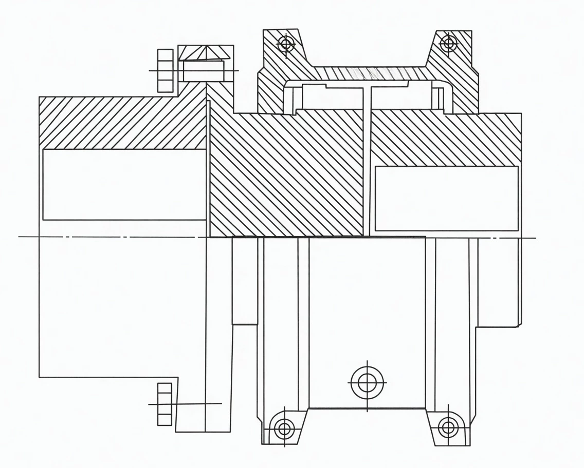
Fig. 2 – JSD Single Flange Grid Coupling cross-section and dimensional drawing
Technical Specifications – JSD Single Flange Grid Coupling
Full specifications for all 19 JSD sizes. Bore diameter listings show flange-side and shaft-side options separated by slashes where applicable.
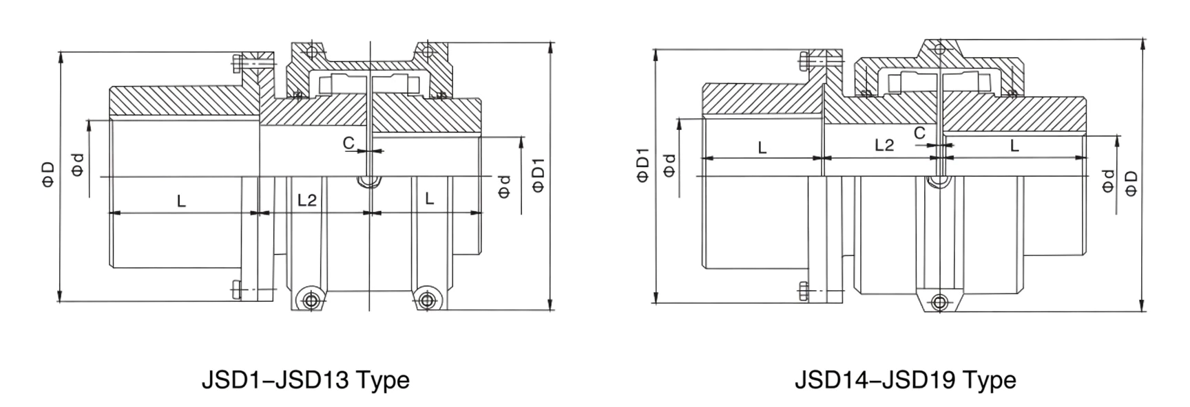
Fig. 3 – JSD Single Flange Grid Coupling complete dimensional reference
| Model | Nominal Torque Tn (N·m) |
Max Speed (rpm) |
Shaft Bore d (Flange d1 / Shaft d) |
Flange L (mm) |
Shaft L (mm) |
L2 Min (mm) |
L2 Max (mm) |
D (mm) | D1 (mm) | C (mm) | Weight (kg) |
Lubricant (kg) |
|---|---|---|---|---|---|---|---|---|---|---|---|---|
| JSD1 | 45 | 3,600 | 18–28 / 25, 28 / 30, 32, 35 | 35 | 47 | 45 | 102 | 97 | 86 | 3 | 2.9 | 0.027 |
| JSD2 | 140 | 3,600 | 22–28 / 30–38 / 40, 42 | 41 | 47 | 45 | 106 | 94 | – | 3 | 3.9 | 0.041 |
| JSD3 | 224 | 3,600 | 25–38 / 40–56 | 54 | 50 | – | 109 | 114 | 113 | 3 | 5.9 | 0.054 |
| JSD4 | 400 | 3,600 | 32–38 / 40–56 / 60, 63, 65 | 60 | 60 | 56 | – | 135 | 125 | 3 | 8.98 | 0.068 |
| JSD5 | 630 | 3,600 | 40–48 / 50, 55, 56 / 60–80 | 73 | 63 | – | 166 | 148 | 114 | – | 13.5 | 0.086 |
| JSD6 | 900 | 3,600 | 48–56 / 60–75 / 80, 85 | 79 | 76 | 64 | 166 | 159 | 152 | – | 17.5 | 0.113 |
| JSD7 | 1,800 | 3,600 | 55–75 / 80, 85, 90, 95 / – | 88 | 89 | 93 | 204 | 190 | 178 | 3 | 28.6 | 0.172 |
| JSD8 | 3,150 | 3,600 | 65–95 / 100, 110 / – | 98 | 100 | 93 | 204 | 211 | 210 | 3 | 42.9 | 0.254 |
| JSD9 | 5,600 | 2,440 | 80–95 / 100–125 / 130 | 120 | 90 | 103 | 205 | 251 | 251 | 5 | 70.8 | 0.426 |
| JSD10 | 8,000 | 2,250 | 90, 95 / 100–125 / 130–150 | 127 | 104 | 106 | 205 | 270 | 276 | 5 | 95.7 | 0.508 |
| JSD11 | 12,500 | 2,025 | 95–125 / 130–150 / 160, 170 | 150 | 120 | 125 | 205 | 308 | 319 | 6 | 139 | 0.735 |
| JSD12 | 18,000 | 1,800 | 110–150 / 160–180 / 190 | 162 | 134 | 130 | – | 346 | 346 | 6 | 190 | 0.907 |
| JSD13 | 25,000 | 1,650 | 120–200 | 152 | 184 | 135 | – | 384 | 359 | – | 259 | 1.13 |
| JSD14 | 35,500 | 1,500 | 100–180 / 190, 200 / 240, 250 | 173 | 183 | 175 | 185 | 453 | 426 | – | 342.77 | 1.95 |
| JSD15 | 50,000 | 1,350 | 110–125 / 130–220 / 240–280 | 186 | 198 | 180 | 205 | 501 | 457 | – | 434.48 | 2.81 |
| JSD16 | 63,000 | 1,220 | 125 / 130–220 / 240, 250 / 280–320 | 220 | 216 | 194 | 224 | 566 | 527 | 10 | 641.96 | 3.49 |
| JSD17 | 90,000 | 1,100 | 100–125 / 130–260 / 280–320 | 249 | 239 | 202 | 247 | 630 | 590 | 10 | 859.88 | 3.77 |
| JSD18 | 125,000 | 1,050 | 110–150 / 160–250 / 280–320 / 340, 360 | 276 | 259 | 207 | 267 | 676 | 660 | – | 1,127.74 | 4.4 |
| JSD19 | 160,000 | 900 | 110–150 / 160–180 / 190–320 / 340–380 | 305 | 279 | 224 | 289 | 757 | 711 | – | 12.4 | 5.63 |
Industry Applications
Thermal Power Stations
Coupling turbine output flanges to generator input shafts, or connecting boiler feed pump gearboxes to motor shafts, where one interface is flanged and the other is keyed.
Steel Rolling Mills
Linking flanged spindle couplings on rolling stands to keyed motor shafts, absorbing the severe torsional reversals inherent in hot and cold rolling processes.
Pulp & Paper Mills
Connecting gearbox flanges to paper machine drive shafts on press sections, dryer groups, and winder drives where precise torque control preserves sheet quality.
Water Infrastructure
Driving large vertical turbine pumps and axial flow pumps in flood control stations and irrigation networks where mixed flange/shaft interfaces are common in pump-motor assemblies.
GBC grid coupling product range – engineered for reliability across all industrial sectors
Customer Feedback
★★★★★ – Coal-Fired Power Plant, USA
Industry: Power Generation | Application: Boiler Feed Pump Drive
“We installed JSD15 couplings between our 4,160V motor shafts and gearbox flanges on three 50,000 N·m boiler feed pump drives. The single flange saved us the cost of adapter flanges we previously needed with our old disc couplings. Vibration readings after commissioning were 40% below our alarm setpoints.”
– Vibration Analyst, Midwest Power Station
★★★★★ – Integrated Steel Works, Turkey
Industry: Steel Manufacturing | Application: Hot Strip Mill Drive
“Our hot strip mill finishing stands demand couplings that withstand 18,000 N·m with frequent torque reversals during cobble recovery. The JSD12 has performed flawlessly through over 8,000 rolling campaigns with no spring degradation, and the mixed flange-shaft design matched our existing drive train interfaces without modification.”
– Rolling Mill Superintendent, Iskenderun Works
★★★★☆ – Pulp Mill, Finland
Industry: Pulp & Paper | Application: Press Section Gearbox Coupling
“The JSD8 couplings on our press section gearbox-to-motor connections resolved a persistent vibration issue at 47 Hz that was causing accelerated bearing wear. The serpentine spring shifted the natural frequency sufficiently to avoid resonance. We recommend pre-ordering spare springs to minimize turnaround downtime during annual shutdowns.”
– Reliability Manager, Kymi Mill Complex
Frequently Asked Questions
Order JSD Single Flange Grid Couplings From GBC
GBC delivers JSD single flange grid couplings with independent bore machining on flange and shaft sides, custom flange drilling to your specifications, and optional ISO 1940 dynamic balancing. Every unit ships with dimensional inspection reports and material certificates.
Request a JSD Quote
Explore Coupling Range
Response within 24 hours | Custom bores available
The JSD Single Flange Grid Coupling features one flanged hub and one keyed shaft hub, bridging flange-connected and shaft-mounted equipment. With 19 sizes from 45 to 160,000 N·m, it provides the flexibility needed for mixed-interface drive trains in power generation, steel production, and heavy process machinery.
Related products
-
LMZ-II Type Plum Blossom Coupling with Integral Brake Wheel
-
LMZ-I Type Plum Blossom Coupling with Split Brake Wheel
-

SWP-B Short Flexible Universal Joint Couplings
-
NGCLZ Drum Shape Gear Coupling with Brake Drum | Intermediate Shaft Type
-
GCLD Drum Shape Gear Coupling
-
DJM Type Single Flexible Diaphragm Coupling