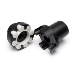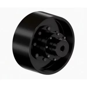
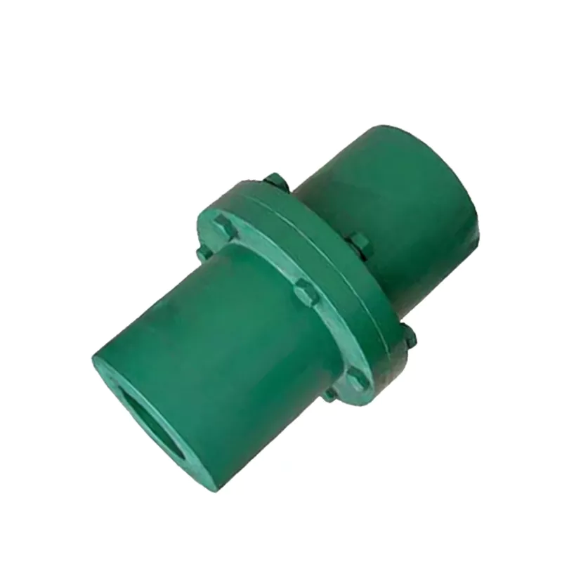
GY/GYS/GYH Flange Coupling
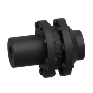
GB/T5843-2003 GY/GYS/GYH flange coupling — the most widely adopted rigid coupling in industrial practice. Three sub-types cover torque from 25 to 100,000 N.m across 13 sizes. GY uses reamed-bolt alignment; GYS uses tongue-and-groove tenon; GYH uses an alignment ring. Suitable for steel mills, cement kilns, marine, and heavy process drives.
MOQ: 50 pcs. Minimum order value USD 1,500; mixed orders and trial quantities welcome.
The GY, GYS, and GYH flange couplings represent the most comprehensively adopted rigid coupling design in Chinese national standard mechanical engineering practice, now widely specified across Australian industrial projects. Manufactured to GB/T5843-2003, this coupling family delivers exceptional torque transmission across an extraordinary range — from 25 N.m for compact machinery applications up to 100,000 N.m for the largest GY13/GYS13/GYH13 size — making it suitable for almost every conceivable heavy industrial application.
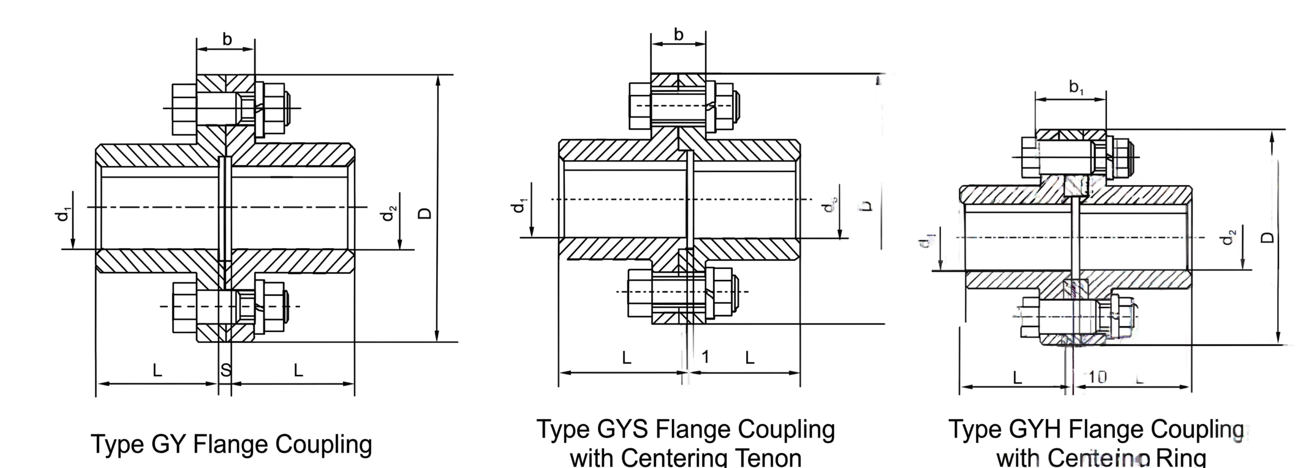
Three structural sub-types serve different assembly and alignment requirements within the same dimensional family. The GY type uses a reamed-hole fitted bolt arrangement (铰制孔螺栓对中) that aligns the coupling halves without axial movement during assembly, making it highly suitable where the connected equipment cannot be moved along the shaft axis. The GYS type incorporates a tongue-and-groove alignment tenon between the faces, offering excellent centring convenience but requiring axial movement during assembly. The GYH type uses an alignment ring (环) centring mechanism, offering an intermediate option. All three sub-types share identical outer diameters, bolt dimensions, and hub bore specifications within each size number, ensuring full interchangeability of flanges across the GY product family.
The marking standard for this coupling series follows a clear convention. For example: GYS6 45×84 GB/T5843-2003 identifies a GYS-type (alignment tenon) size 6 coupling with both active and driven halves featuring Y-axis holes and A-type keyways at 45mm bore diameter and 84mm hub length. This standardised notation simplifies procurement, maintenance documentation, and spare parts management across large plant installations.
Three Sub-Type Structural Characteristics
GY Type — Reamed Bolt Alignment
The GY flange coupling uses precision-reamed bolt holes to achieve coupling concentricity. The fitted bolts act as both fasteners and alignment elements, passing through reamed holes in both flanges to centre them without requiring any axial displacement of the shaft assembly. This makes the GY type the preferred choice when axial movement is restricted — for instance, in assemblies with fixed thrust bearings at both ends.
GYS Type — Tongue-and-Groove Tenon
The GYS variant adds a machined tongue on one flange face that locates into a matching groove on the opposing half. This provides rapid self-centring during assembly and excellent resistance to radial forces in service. Assembly does require axial movement to engage the tenon, making GYS most suitable for drives where the shaft can slide freely during installation. The GYS is particularly favoured in food processing, textile, and chemical plant applications.
GYH Type — Alignment Ring
The GYH type employs a separate annular alignment ring fitted between the two flange faces to achieve centring. This approach is advantageous where the coupling may need to be disassembled and reassembled in service, as the ring can be reused without requiring remachining of the flange faces. The GYH is commonly specified in power station auxiliaries, marine applications, and process plant drives subject to regular planned maintenance intervals.
All three sub-types share the same fundamental flange geometry: the same outer diameter D, bolt circle diameter b, flange width dimensions b and b₁, and the same shaft hole bore options within each size number. This means that in a plant with mixed GY, GYS, and GYH assemblies, spare flanged hubs are interchangeable within each size — reducing inventory requirements substantially.
Technical Specifications — GY, GYS, GYH Flange Coupling (GB/T5843-2003)
| Type No. | Nominal Torque (N.m) | Max Speed (rpm) | Bore d1, d2 (mm) | Hub Length Y-type (mm) | Hub Length J-type (mm) | D (mm) | b (mm) | b₁ (mm) | S (mm) | Rot. Inertia (kg·m²) | Weight (kg) |
|---|---|---|---|---|---|---|---|---|---|---|---|
| GY1/GYS1/GYH1 | 25 | 12000 | 12–19 | 32 | 27 | 80 | 26 | 42 | 6 | 0.0008 | 1.16 |
| GY2/GYS2/GYH2 | 63 | 10000 | 16–25 | 42 | 30 | 90 | 28 | 44 | 6 | 0.0015 | 1.72 |
| GY3/GYS3/GYH3 | 112 | 9500 | 20–28 | 52 | 38 | 100 | 30 | 46 | 6 | 0.0025 | 2.38 |
| GY4/GYS4/GYH4 | 224 | 9000 | 25–35 | 62 | 44 | 105 | 32 | 48 | 6 | 0.003 | 3.15 |
| GY5/GYS5/GYH5 | 400 | 8000 | 30–42 | 82 | 60 | 120 | 36 | 52 | 8 | 0.007 | 5.43 |
| GY6/GYS6/GYH6 | 900 | 6800 | 38–50 | 112 | 84 | 140 | 40 | 56 | 8 | 0.015 | 7.59 |
| GY7/GYS7/GYH7 | 1600 | 6000 | 48–63 | 112 | 84 | 160 | 40 | 56 | 8 | 0.031 | 13.1 |
| GY8/GYS8/GYH8 | 3150 | 4800 | 60–75 | 142 | 107 | 200 | 50 | 68 | 10 | 0.103 | 27.5 |
| GY9/GYS9/GYH9 | 6300 | 3600 | 75–100 | 172 | 132 | 260 | 66 | 84 | 10 | 0.319 | 47.8 |
| GY10/GYS10/GYH10 | 10000 | 3200 | 90–125 | 212 | 167 | 300 | 72 | 90 | 10 | 0.720 | 82.0 |
| GY11/GYS11/GYH11 | 25000 | 2500 | 120–160 | 252 | 202 | 380 | 80 | 98 | 10 | 2.278 | 162.2 |
| GY12/GYS12/GYH12 | 50000 | 2000 | 150–200 | 302 | 242 | 460 | 92 | 112 | 12 | 5.923 | 285.6 |
| GY13/GYS13/GYH13 | 100000 | 1600 | 190–250 | 352 | 282 | 590 | 110 | 130 | 12 | 19.978 | 611.9 |
Note: Weight and rotational inertia values are calculated for GY/J-type shaft holes with Y-type bore assembly at minimum shaft diameter. All dimensions in mm unless otherwise stated.
Industry Applications Across Australian and Asia-Pacific Projects
The GY/GYS/GYH coupling range serves the most demanding industry segments owing to its extreme torque capacity at the large end of the scale and its clean, compact form factor at the small end. Common deployment scenarios include:
Steel and Metals Processing
Rolling mill main drives, ladle transfer cars, continuous caster pinch rolls, and bar and rod mill finishing stands. GY11 through GY13 sizes regularly appear in heavy primary metal processing facilities across Port Kembla and Whyalla, transmitting tens of thousands of N.m under cyclic shock loading.
Marine and Port Equipment
Shipboard auxiliary drives, deck crane slewing rings, harbour crane hoist drives, and bulk materials ship loaders. GYH-type alignment ring couplings are popular in marine settings because the ring can be replaced during routine service without removing the flanged hubs from their shafts.
Paper and Pulp Production
Kraft pulp digesters, paper machine press section rolls, tissue machine Yankee driers, and calendar stack drives. The GYS tongue-and-groove alignment simplifies coupling half replacement during scheduled press roll changes — a task performed on short maintenance windows.
Cement and Aggregate Production
Rotary kiln main drives, raw mill circuits, clinker cooler fans, and cement grinding mills. The extreme torque capability of GY10 through GY13 makes this range standard specification in Australian cement plant main drives operating under start-up overload conditions.
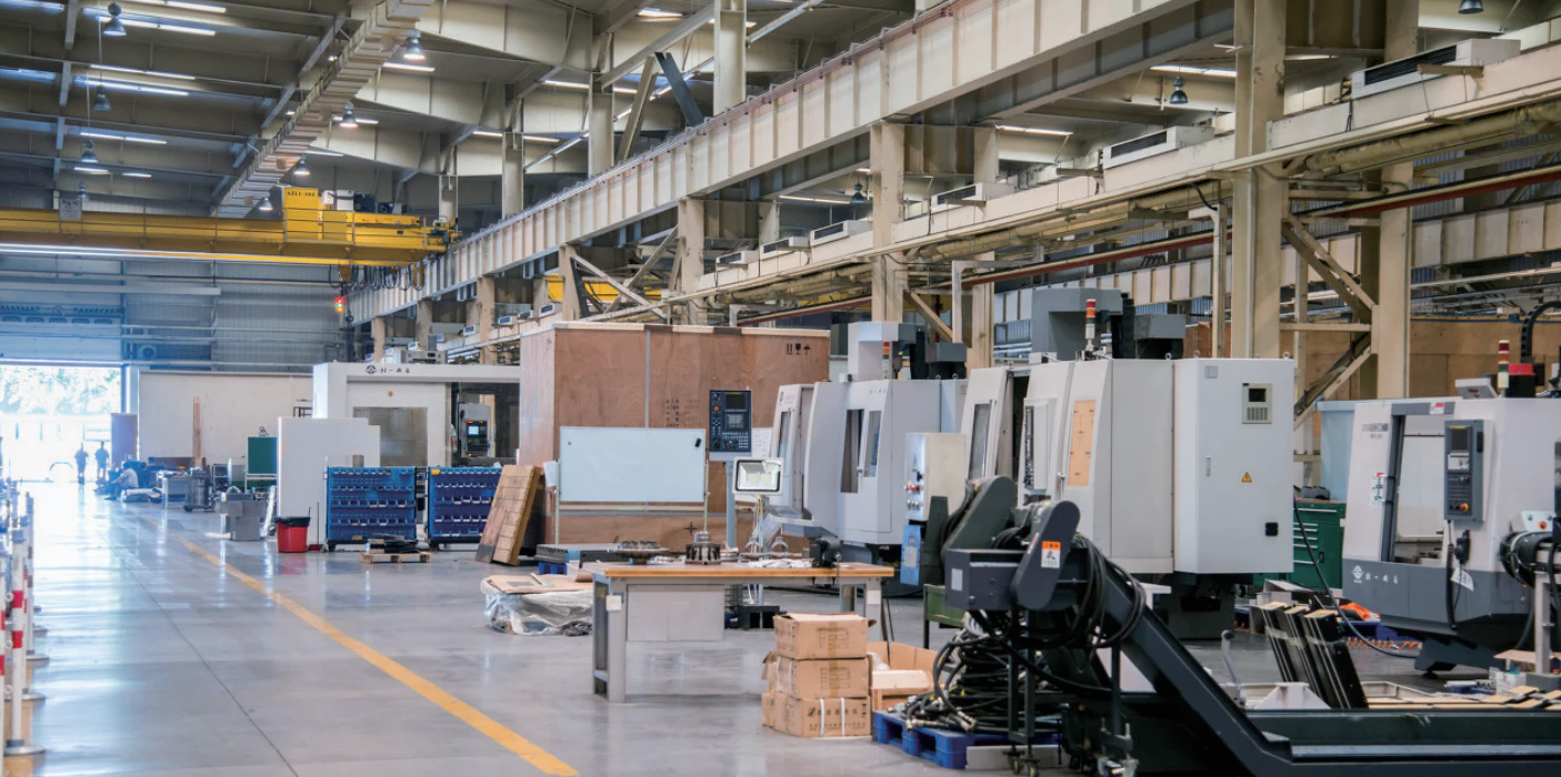
Production of the GY/GYS/GYH range uses dedicated horizontal boring machines for large-size coupling machining (GY10 and above), with CMM dimensional verification on all critical dimensions including bore diameter, bore roundness, flange face perpendicularity, and bolt hole position accuracy. For related coupling types, see our complete rigid coupling product range and the full couplings catalogue.
Customer Reviews and Project Case Studies
★★★★★
Australia — Steel Mill Main Drive Replacement, South Australia
Industry: Steel Production | Application: Rolling mill main coupling, GY11 size, 25,000 N.m rated
"We needed a direct replacement for worn flanged couplings on our hot strip mill entry coiler. The GY11 size matched our existing bolt circle and hub bore exactly. Machining quality was excellent — we ran CMM checks on arrival and everything was within drawing. The mill has now run two production campaigns since installation with no coupling-related stoppages."
— Mechanical Engineer, South Australian Steel Facility
★★★★★
Japan — Chemical Plant Compressor Drive, Yokohama
Industry: Petrochemical Processing | Application: GYH8 alignment ring type, 3150 N.m, 4800 rpm
"The GYH alignment ring design was specified by our rotating equipment consultant for this application as it allows coupling inspection without shaft removal. On our second planned turnaround we inspected and reinstalled the same ring — no wear issues detected. A very practical design for in-service maintenance."
— Rotating Equipment Specialist, Yokohama Chemical Complex
★★★★☆
United Kingdom — Paper Mill Press Section, Scotland
Industry: Paper and Pulp | Application: GYS6 tongue-and-groove type, 900 N.m
"We ordered GYS6 couplings as part of a press roll refurbishment programme. The tongue-and-groove alignment meant our fitting team could swap coupling halves during a scheduled roll change without needing to re-align — a significant time saving on a tight maintenance window. Quality was consistent across all twelve units supplied."
— Maintenance Planning Lead, Scottish Paper Mill
★★★★★
Australia — Cement Kiln Drive, Victoria
Industry: Cement Production | Application: GY12 size, 50,000 N.m, rotary kiln secondary drive
"Sourced GY12 coupling hubs for our rotary kiln drive upgrade. Bore machining was completed in our workshop to match the existing pinion shaft. The coupling has been in continuous service through two kiln campaigns — approximately 14 months of operation — without any issues. Very happy with the quality of the raw castings and the machining of the flange face."
— Plant Mechanical Engineer, Victorian Cement Facility
Frequently Asked Questions
What is the key difference between GY, GYS, and GYH sub-types?
All three share the same flange outer diameter, bolt pattern, and bore specifications for each size number. The GY type uses precision reamed bolt holes for alignment and does not require axial shaft movement during assembly. The GYS type uses a tongue-and-groove tenon for self-centring but requires axial movement to engage. The GYH type uses a separate alignment ring between the faces. Selection depends on your assembly constraints and maintenance access requirements.
Can the two halves of a GY, GYS, or GYH coupling be mixed?
Within each size number, GY and GYH flanged hubs share the same outer geometry and bolt circles, so a GY half can mate with a GYH half using the alignment ring. GYS halves require matching GYS-type opposing faces for the tongue-and-groove engagement. If mixing sub-types is required, please consult our technical team for confirmation of dimensional compatibility before ordering.
What is the maximum torque achievable in the GY/GYS/GYH range?
The GY13/GYS13/GYH13 size is rated at 100,000 N.m nominal torque, with an outer diameter of 590mm and maximum bore diameter of 250mm. This is among the highest torque capacities available in a standard GB-series flanged coupling. For torques beyond this range, custom-engineered solutions are available on enquiry.
Are taper (cone) shaft bores available for GY flange couplings?
Yes. In addition to standard Y-type cylindrical bores and J-type keyed bores, taper (cone) bores can be supplied to order. Custom bore specifications should include the taper ratio, large and small bore diameters, hub length, and keyway requirements if applicable. These are supplied as non-standard items on a made-to-order basis.
How do I read the GB/T5843-2003 coupling designation marking?
The format is: [Sub-type][Size] [Bore Diameter] x [Hub Length] GB/T5843-2003. For example, GYS6 45x84 GB/T5843-2003 identifies a GYS (tongue-and-groove) size 6 coupling with a 45mm bore and 84mm hub length. Both halves carry the same marking when bores are equal, or separate markings for each half when different bore sizes are required on active and driven ends.
Enquire About GY/GYS/GYH Flange Couplings for Your Application
We supply B2B customers across Australian mining, marine, cement, steel, and process industries with GB/T5843-2003 flanged couplings in all thirteen size grades and three sub-types. Custom bore machining, taper bores, split shipments, and material test certificates are available on request. Our technical team can assist with size selection, interchangeability confirmation, and application engineering support.
GB/T5843-2003 GY/GYS/GYH flange coupling — the most widely adopted rigid coupling in industrial practice. Three sub-types cover torque from 25 to 100,000 N.m across 13 sizes. GY uses reamed-bolt alignment; GYS uses tongue-and-groove tenon; GYH uses an alignment ring. Suitable for steel mills, cement kilns, marine, and heavy process drives.
MOQ: 50 pcs. Minimum order value USD 1,500; mixed orders and trial quantities welcome.