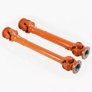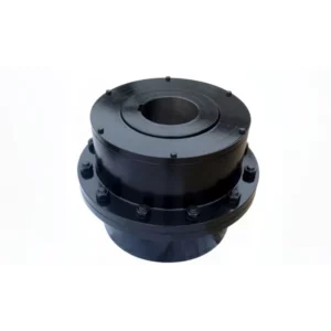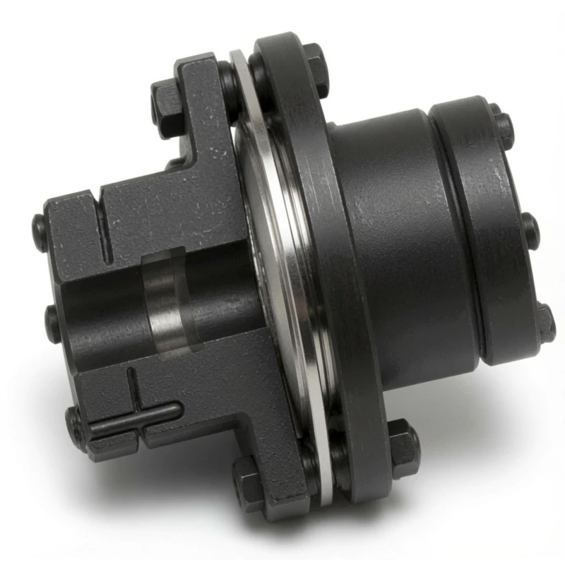
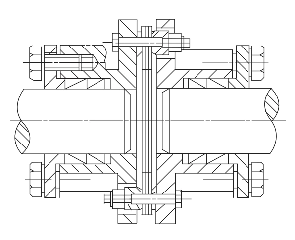
DJM-Z1 Type Locking Device Single Flexible Diaphragm Coupling
The DJM-Z1 Type Single Flexible Diaphragm Coupling with Locking Device replaces the conventional keyway with an interference-fit locking collar, eliminating all drive backlash and rotational play at the shaft connection. Available in 7 sizes from 33 N·m to 1,270 N·m at up to 20,000 rpm, it is the standard choice for CNC machine tool servo drives, ball-screw feed axes, and precision positioning systems that demand absolute zero-backlash performance.
What Is a DJM-Z1 Locking Device Diaphragm Coupling?
The DJM-Z1 single flexible diaphragm coupling with locking device addresses the fundamental limitation of keyway-connected couplings in precision drives: the small but non-zero clearance between a key and its keyway produces rotational backlash that degrades positioning accuracy. In CNC machine tools, ball-screw feed systems, and servo-driven positioning stages, even 0.01° of backlash translates to dimensional error at the tool — unacceptable in high-precision machining.
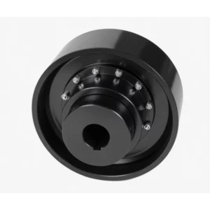
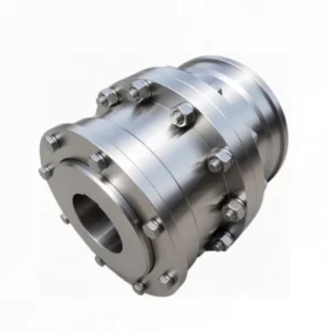
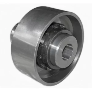
The DJM-Z1 solves this by substituting the keyway with a Z1-type locking device (interference-fit locking collar) on each hub. As the locking bolts are progressively tightened, the collar compresses uniformly around the shaft, creating a friction-grip connection with zero play. The result is a coupling that transmits torque without any rotational slip or angular clearance between shaft and hub — the same high-speed, high-temperature, lubrication-free characteristics of the standard DJM diaphragm pack, combined with absolute zero backlash at the shaft interface.
A second significant advantage of the locking device connection is ease of installation and removal. A keyway requires an interference or close-clearance fit between bore and shaft — installing and removing requires pressing equipment and heating. The Z1 locking device can be tightened and released with a standard hex key wrench, making coupling swap and shaft repositioning a straightforward workshop task.
Z1 Locking Device vs Standard Keyway — Direct Comparison
| Feature | DJM-Z1 (Locking Device) | DJM Standard (Keyway) |
|---|---|---|
| Rotational backlash | Zero | Small (key clearance) |
| Bore tolerance required | h8 (≥38 mm) / h6 (<38 mm) | H7 interference or transition fit |
| Installation tool | Hex key wrench only | Press / heater required |
| Shaft keyway required | No | Yes |
| Bore diameter at same OD | Larger (no keyway depth) | Standard |
| Repositioning shaft axially | Simple — release and re-tighten | Requires press-out and re-pressing |
| Repeat positioning accuracy | High — repeatable to shaft stop | Depends on fit quality |
DJM-Z1 Coupling Specifications and Dimensions
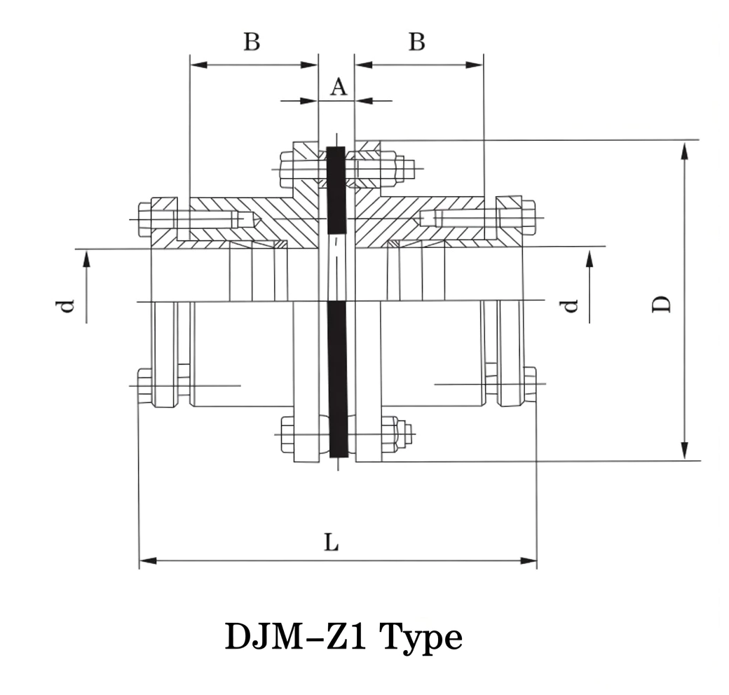
Materials
Diaphragm pack: stainless steel sheet. Hub flanges: alloy steel (precision machined). Locking device: hardened alloy steel. Bolts: high-tensile alloy steel grade 12.9. All components precision-balanced at the machining stage for high-speed servo applications.
Ordering Mark Examples
→ Size 02, Y-type taper locking bore, drive shaft 19 mm / driven shaft 19 mm
DJM-Z,03 YT19 / YA18×30
→ Size 03, Y taper-lock drive 19 mm / Y-bore A-keyway driven 18 mm × L30 mm
Complete Parameter Table — DJM-Z1 Sizes 01–07
Angular compensation: 1° all sizes · Shaft tolerance: d ≥ 38 mm use h8; d < 38 mm use h6. Cone coupling: shaft diameter refers to large end. Z7B locking device can be replaced with Z10 type.
| Size | Bore d mm | D mm | L mm | A mm | B mm | Weight kg | Max Speed rpm | Nom. Torque N·m | Axial mm | Angle |
|---|---|---|---|---|---|---|---|---|---|---|
| 01 | 8–22 | 68 | 90 | 6.1 | 26 | 0.85 | 20,000 | 33 | ±0.8 | 1° |
| 02 | 10–32 | 81 | 95 | 6.6 | 26 | 1.2 | 20,000 | 90 | ±1.0 | 1° |
| 03 | 10–35 | 93 | 110 | 8.4 | 29 | 1.7 | 18,000 | 173 | ±1.2 | 1° |
| 04 | 10–42 | 104 | 124 | 11.2 | 34 | 2.7 | 15,000 | 245 | ±1.4 | 1° |
| 05 | 15–50 | 128 | 136 | 11.7 | 42 | 6.5 | 13,000 | 420 | ±1.6 | 1° |
| 06 | 15–60 | 143 | 158 | 11.7 | 48 | 8.9 | 12,000 | 772 | ±1.8 | 1° |
| 07 | 20–70 | 168 | 176 | 14 | 58 | 15.8 | 10,000 | 1270 | ±2.5 | 1° |
Note: Size 01 starts at DJM-Z1,01; the catalogue prefix DJM-Z designates the locking-device series. Custom bore diameters and extended shaft lengths available on request.
How to Select a DJM-Z1 Coupling
Design Torque Calculation
K = service factor (1.5–2.0 for servo motor with moderate shock) | P = rated power (kW) | N = max speed (rpm)
Selection Steps for CNC and Servo Applications
- Calculate TC: For servo drives apply K = 1.5–2.0 to account for acceleration torque peaks. Use peak motor torque (not rated) where acceleration cycles are frequent.
- Select size: Choose the DJM-Z1 size where Tn ≥ TC. Confirm bore range includes both shaft diameters.
- Verify shaft tolerance: Shaft surface must be h8 (diameter ≥ 38 mm) or h6 (diameter < 38 mm) for the locking device to achieve full grip. Do not use Z1 on shafts with corrosion or surface defects.
- Check speed: Operating speed must be below the rated maximum. For high-cycle servo applications, confirm the coupling is dynamically balanced to the required grade if speed exceeds 5,000 rpm.
- Specify hole form: YT = taper lock (Z type); YA = standard Y bore with A-keyway. Mixed configurations are available — taper lock on the motor shaft, keyway on the ball-screw end, or both ends taper-locked.
DJM-Z1 vs DJM Standard — When to Choose Z1
- Positioning accuracy is a specification requirement (CNC axes, coordinate measuring, robotics)
- The drive undergoes frequent direction reversals (thread cutting, oscillating servo motion)
- The shaft has no keyway (smooth motor shaft, ground ball-screw journal)
- Shaft axial repositioning is required without hub removal (common on adjustable-pitch ball-screw setups)
- The customer specifies zero backlash in the drive train (ISO tolerance H/h fits)
Metal Diaphragm Coupling Range — Related Types
The DJM-Z1 covers torque up to 1,270 N·m. For higher torques or larger bores with locking-device connection, the DJM/SJM-YP locking disc series extends the zero-backlash concept to 8,100,000 N·m.
9.8–8,100,000 N·m · 41 sizes · Keyway · General industrial high-speed drives
9.8–8,100,000 N·m · 41 sizes · Keyway · Greater radial compensation
33–1,270 N·m · 7 sizes · Z1 locking device · Zero backlash · CNC and servo drives
Cone-hub connection · CNC machine feed shafts · Alternative to Z1 locking device · Larger bore at same OD
33–8,100,000 N·m · Z7B locking disc · Zero backlash · Wide torque range
420–25,410 N·m · Integrated disc brake · Servo brake drives
40–180,000 N·m · Rod-type · Long shaft spans
Maximum compensation · Rod-type · High misalignment drives
DJM-Z1 Applications
The DJM-Z1 is the primary product designed for this application. Servo motor to ball-screw connections on milling, turning, and grinding machines require zero backlash so that the commanded tool position matches the actual table position. The locking device eliminates key-clearance backlash; the diaphragm pack compensates for slight parallel offset between motor and ball-screw centrelines without imposing side loads on either set of bearings.
Robot joint drives operate with frequent direction reversals under dynamic loads. Keyway clearance that is acceptable on continuous-rotation drives becomes significant positioning error on oscillating robot axes. The DJM-Z1's zero-backlash locking device maintains TCP (tool centre point) accuracy across the full range of joint motion.
Wafer handling equipment, die bonding machines, and PCB positioning stages use DJM-Z1 couplings where micrometre-level repeat accuracy is required. The all-metal construction is compatible with clean-room environments, and the absence of elastomeric elements ensures no outgassing in vacuum chambers.
CMM probe positioning drives must achieve sub-micron repeat positioning. The DJM-Z1's zero-backlash and torsional stiffness prevent measurement uncertainty caused by coupling compliance during deceleration — a failure mode well documented with elastomeric couplings on high-precision CMM axes.
Diagnostic imaging rotary stages, centrifuge drives, and automated sample handling use DJM-Z1 for its zero-backlash performance and the locking device's vibration-free grip (no keyway fretting generates contamination particles). The all-metal construction is autoclave-compatible for sterile equipment applications.
Telescope focusing drives, laser beam positioning systems, and optical bench rotation stages demand torsional stiffness combined with zero-clearance shaft connection. The DJM-Z1 provides both, with the diaphragm pack isolating the servo drive's motor vibration from the optical element.
Installation and Maintenance
Locking Device Installation Steps
- Shaft preparation: Clean shaft ends; remove all oil, burrs, and scale. Confirm shaft diameter tolerance is h8 (≥38 mm diameter) or h6 (<38 mm diameter). No keyway cutting required — smooth round shaft is correct.
- Coupling position: Slide the coupling to the required axial position on both shafts. Confirm the gap between hub faces equals the diaphragm pack assembly thickness.
- Locking bolt pre-tightening: Finger-tighten all locking bolts evenly around the collar. This seats the locking device concentrically before load is applied.
- Progressive torque-up: Using a calibrated torque wrench, tighten locking bolts in a cross-pattern to 1/3 specified torque, then 2/3, then full. Multiple passes ensure uniform collar compression and prevent cocking of the locking ring.
- Diaphragm assembly: Fit diaphragm pack between hub flanges; torque mounting bolts in cross-pattern in three passes as per specification.
- Verification: Check axial position has not shifted during locking. Rotate by hand; confirm smooth operation.
Removal:Release locking bolts progressively in the same cross-pattern used for tightening. The locking device releases concentrically, allowing the coupling to slide off the shaft without damage to either the shaft or the hub. This is a major advantage over pressed-fit hubs which require special pulling equipment.
Fault Diagnosis
| Symptom | Likely Cause | Action |
|---|---|---|
| Position error on servo drive | Locking device has slipped axially; insufficient bolt torque | Recheck shaft diameter tolerance; re-torque locking bolts to spec |
| Vibration at high speed | Locking collar cocked (uneven tightening); shaft misalignment | Release and re-torque evenly; check alignment with dial gauge |
| Coupling slipping under torque | Shaft diameter out of tolerance (too small); oil contamination | Verify shaft tolerance; clean shaft; use Z10 device for larger bore |
| Diaphragm crack | Misalignment exceeds 1° limit; torque overload | Replace diaphragm; recalculate TC; re-align shafts |
DJM-Z1 vs Alternative Servo Coupling Types
vs Bellows Coupling: Metallic bellows couplings also provide zero backlash but the corrugated bellows element has lower torsional stiffness than the DJM diaphragm pack and is more susceptible to fatigue failure under axial oscillation. The DJM-Z1's flat diaphragm pack is more robust under combined axial and angular loading, and allows higher torque capacity at the same OD.
vs Jaw Coupling with Zero-Backlash Spider: Polyurethane zero-backlash jaw couplings achieve very low but non-zero backlash through pre-compression of the spider element. This pre-load also introduces a speed-dependent torsional stiffness that varies with temperature and age. The DJM-Z1's all-metal stiffness is constant across the full temperature and speed range, giving predictable servo loop behaviour.
vs DJM Standard Keyway Type: For applications that do not require zero backlash — fans, pumps, generators — the DJM keyway type is a more cost-effective choice. The Z1 locking device adds cost and requires closer shaft diameter tolerances. Specify Z1 only where backlash is a measurable performance requirement.
Customer Case Studies
Australia — CNC Machine Tool OEM
Standardised the DJM-Z1,04 and Z1,05 across our 5-axis machining centre range. The zero-backlash locking device eliminated the positioning drift we saw with keyway couplings on our X and Y axes under repeated reversal cycles. Retrofit installations take under 20 minutes — the hex-key release is a significant productivity gain over our previous pressed-fit hubs.
Machine Design Engineer, Victoria AU
★★★★★
Taiwan — Semiconductor Equipment
DJM-Z1,02 and Z1,03 on wafer transport rotary stages in a 300 mm fab. The coupling's clean-room compatibility and absence of outgassing material were non-negotiable for our process environment. Repeat positioning accuracy measured at ±0.003° across 2 million cycles — well within our 0.01° specification.
Process Equipment Engineer, Hsinchu TW
★★★★★
Germany — Precision Machining
We build 5-axis grinding machines for the aerospace supply chain. The DJM-Z1,05 on our B-axis tilt drive replaced a bellows coupling that was failing under the combined angular and axial loads from the grinding cycle. In 18 months of continuous operation, no coupling failures. Backlash measured at assembly: undetectable with our 0.001° measurement system.
Head of R&D, Baden-Württemberg DE
★★★★☆
USA — Industrial Robot Integrator
Using DJM-Z1,03 on the wrist joint of a custom 6-axis robot for automotive assembly. The zero-backlash performance is critical for our path accuracy specification. The locking device lets us adjust shaft axial position during commissioning without returning the joint to the workshop — saved us two days on the first installation.
Controls Engineer, Michigan US
★★★★★
Frequently Asked Questions
▶ What is the Z1 locking device and how does it achieve zero backlash?
The Z1 locking device is an interference-fit collar that clamps uniformly around the shaft when its bolts are progressively tightened. Unlike a key, which has a small clearance between the key sides and the keyway walls, the locking collar grips the shaft concentrically with no clearance. There is no rotational play at the shaft-hub interface — the hub rotates with the shaft as a single rigid element. Backlash in a key-connected coupling is typically 0.01°–0.05°; with the Z1 locking device it is zero.
▶ Can the DJM-Z1 coupling be used on a shaft that already has a keyway?
Yes. The Z1 locking device grips the shaft OD regardless of whether a keyway is present. The locking collar spans the keyway, and the clamping force is distributed over the full circumference of the shaft. The keyway does slightly reduce the gripping surface area, so for maximum torque capacity on a keyed shaft, confirm with GBC engineering that the Z1 device is appropriately sized. In most cases the standard Z1 size for the torque requirement is sufficient.
▶ What shaft diameter tolerance is required for the Z1 locking device?
For shaft diameters of 38 mm and above, the shaft tolerance must be h8. For diameters below 38 mm, h6 is required. The tighter h6 tolerance on small shafts compensates for the lower absolute grip force available at small diameters. Shafts with surface defects, corrosion, or out-of-round conditions below these tolerance limits should be dressed before fitting the locking device.
▶ How does the Z7B locking device in the DJM-Z1 differ from Z10?
Both Z7B and Z10 are interference-fit locking collar types but differ in their clamping geometry. Z7B uses a tapered inner surface; Z10 uses a different profile that allows a larger bore diameter at the same coupling OD. The parameter table lists Z7B as standard. Z10 can substitute for Z7B at the same coupling size if a larger shaft diameter is needed — the torque capacity and outer dimensions of the coupling remain unchanged.
▶ Can the DJM-Z1 coupling be dynamically balanced for high-speed servo applications?
Yes. GBC offers shop-balanced assemblies for applications above 5,000 rpm where residual unbalance must be below a specified grade. Dynamic balancing is performed on the complete assembly (both hubs with locking devices and the diaphragm pack). Specify the balance grade (G1.0 is standard for precision servo applications; G2.5 for general industrial) at time of order. Balanced assemblies are typically available within 5–7 working days from the standard lead time.
Source DJM-Z1 Zero-Backlash Couplings for Your Precision Drive
GBC supplies all 7 DJM-Z1 sizes with full dimensional documentation, custom bore configurations, dynamic balance certification, and material certificates. Send us your servo motor shaft diameter, ball-screw journal diameter, torque, and speed requirements and our engineering team will confirm the correct size and locking device specification within 24 hours.
The DJM-Z1 Type Single Flexible Diaphragm Coupling with Locking Device replaces the conventional keyway with an interference-fit locking collar, eliminating all drive backlash and rotational play at the shaft connection. Available in 7 sizes from 33 N·m to 1,270 N·m at up to 20,000 rpm, it is the standard choice for CNC machine tool servo drives, ball-screw feed axes, and precision positioning systems that demand absolute zero-backlash performance.