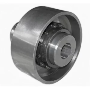
CL Type Gear Coupling
CL type crowned tooth gear coupling per GB/T5843. 16 sizes (CL1–CL16), 40 N·m to 40,000 N·m, up to 4750 RPM. CL compact and CLZ extended sleeve variants. Y, J1, Z bores. Suits pump, fan, conveyor, compressor, and general industrial drives. Custom bore to drawing. Factory direct to Australia.
CL Type Gear Coupling — Crowned Tooth, General Purpose, 16 Sizes
The standard crowned-tooth gear coupling per GB/T5843 for general industrial drives across Australia. Compact, reliable, and economical — available in CL (standard) and CLZ (extended sleeve) configurations. Factory direct from stock or to custom bore specification.
Product Overview
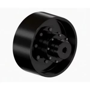
The CL type gear coupling is a crowned tooth (drum shape) flexible coupling per GB/T5843, designed for general industrial shaft-to-shaft connections across the full range of Australian manufacturing, processing, and mining applications. It is the most widely used gear coupling standard in Chinese industry and is well recognised by Australian engineers who work with imported drives, OEM machines from Asia, and locally-built plant that specifies to GB standards.
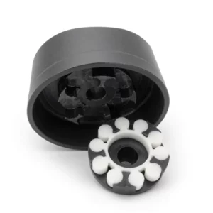
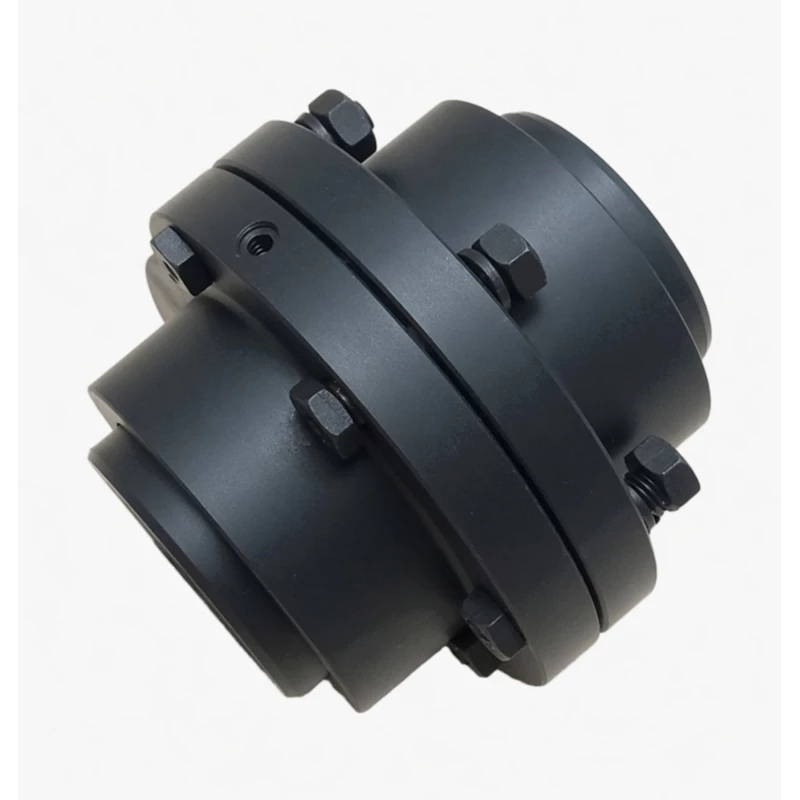
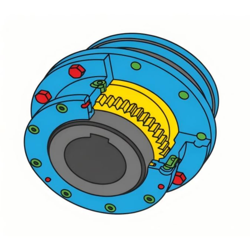
The CL coupling consists of two inner hubs — each with external crowned gear teeth — and a single outer sleeve with internal straight teeth that connects both hubs. The crowned tooth mesh transmits torque while simultaneously accommodating angular, radial, and axial shaft misalignment, protecting motor and gearbox bearings from misalignment-induced loading throughout the drive's service life. Two variants are available: CL (compact standard configuration) and CLZ (with extended outer sleeve for wider shaft gaps), both using the same inner hub geometry and bore specifications.
GBC manufactures CL and CLZ couplings factory-direct and exports to Australian industrial buyers, maintenance engineers, and OEM machine builders, with full documentation support for plant engineering records and AS/NZS-aligned quality plans.
Technical Definition and Working Principle
What Makes the CL a Crowned Tooth Coupling — Not a Straight Tooth Coupling
The fundamental distinction between a CL type crowned tooth gear coupling and a conventional straight tooth gear coupling lies in the geometry of the external teeth on the inner hubs. In a straight tooth gear coupling, the tooth flanks are machined flat and parallel to the shaft axis — producing a line contact that spans the full tooth face width. In the CL's crowned tooth design, the tooth profile is barrel-shaped (crowned) — the tooth is thickest at its mid-point and tapers toward both ends. This geometry creates a Hertzian contact ellipse near the tooth centre rather than a line contact across the full face.
The practical consequence of this difference is substantial: a straight tooth coupling generates contact stress that rises steeply at the tooth edges whenever angular misalignment is present — even small misalignments of 0.1 to 0.2 degrees concentrate the full tooth load at one edge, producing local contact pressures that quickly exceed the tooth surface fatigue limit. The CL's crowned tooth maintains its contact ellipse near the tooth centre even at angular misalignment of up to 1.5 degrees, distributing load uniformly regardless of the shaft angle — eliminating edge loading entirely.
The Three Misalignment Modes and How the CL Handles Each
The CL coupling accommodates three types of shaft misalignment simultaneously, each through a different mechanism in the crowned tooth mesh:
- Angular misalignment — The crowned tooth profile allows the inner hub to tilt relative to the outer sleeve's internal gear ring without generating edge stress. The self-centring nature of the crowned contact keeps the tooth engagement near centre regardless of tilt angle up to the rated maximum of 1.5 degrees per mesh (approximately 1 degree recommended for continuous service).
- Radial (parallel) misalignment — Parallel offset between the two shaft axes causes each coupling half to tilt slightly in the outer sleeve, absorbing the offset as angular displacement at each tooth mesh. The CL coupling accommodates radial offset up to approximately 0.3–0.5 mm for smaller sizes, increasing proportionally with size.
- Axial displacement — Thermal growth of shafts during operation, and installation clearances, are absorbed by the axial sliding of the inner hub teeth within the outer sleeve. The CL accommodates plus or minus 2 to 4 mm of axial displacement without generating thrust forces at the shaft bearings, protecting motor and gearbox bearings from axial loading that causes premature race failure.
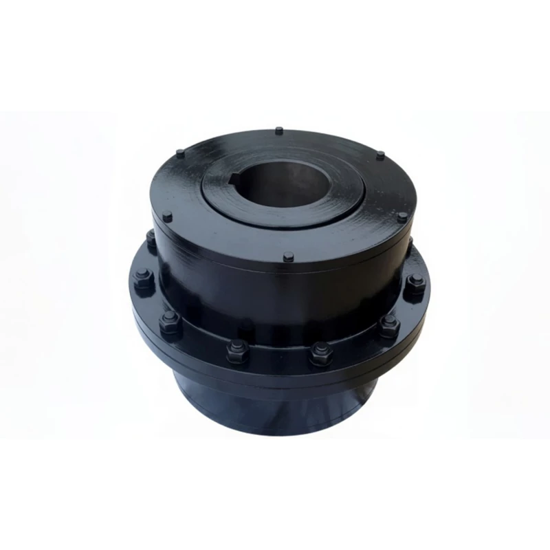
CL Architecture — Inner Hubs, Outer Sleeve, and Lubrication
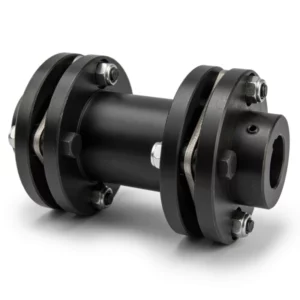
Each CL coupling consists of two identical inner hubs (mounting on their respective shafts via parallel keyway bore or taper bore) and a single outer sleeve. The sleeve has internal straight teeth machined on its bore at both ends, each meshing with one inner hub's external crowned teeth to form the two-mesh torque transmission path. A lubrication fill port at the mid-span of the outer sleeve provides access for grease injection. The sleeve is retained on the hubs by the tooth mesh engagement and a seal arrangement at each end that retains lubricant and excludes contamination.
The CLZ variant uses an extended outer sleeve — longer overall length with the same internal gear tooth geometry at each end — providing a wider shaft gap capability from the same inner hub components. This is equivalent in function to a spacer coupling, allowing the CL hub geometry to be used wherever a longer shaft span is required without changing the inner hub design.
CL vs Other Coupling Types — Performance Comparison
| Feature | CL Type (this product) | Jaw Coupling | Disc Coupling | Straight Tooth Gear Coupling |
|---|---|---|---|---|
| Misalignment Tolerance | High — crowned tooth, up to 1.5 deg | Moderate (elastomer deflects) | Low — disc pack torsionally stiff | Low — edge loading above 0.1 deg |
| Shock Load Tolerance | Excellent — no elastomer to shear | Good (elastomer absorbs, then fails) | Poor — disc pack fatigues rapidly | Poor — edge overload at each shock |
| Torque-to-Size Ratio | High — compact gear mesh | Moderate | Moderate–High | High (but shorter service life) |
| Maintenance | Periodic re-lubrication | Elastomer replacement 1–3 years | Low maintenance (no lube needed) | Periodic re-lube; shorter intervals |
| Torque Range | 40 – 40,000 N·m (CL1–CL16) | Up to ~3000 N·m typically | Wide range | Wide but shorter service life |
CL vs CLZ — Which Variant to Choose
Both CL and CLZ use identical inner hubs for the same size number, share the same torque rating, bore range, and speed limit, and are assembled using the same installation procedure. The only structural difference is the outer sleeve length — and the practical consequence this has for shaft span and installation clearance. The comparison below covers every decision-relevant dimension of the two variants.
| Factor | CL — Standard Compact | CLZ — Extended Sleeve |
|---|---|---|
| Outer Sleeve Length | Standard B dimension per GB/T5843 | Extended B dimension — longer overall assembly |
| Shaft Gap Capability | Standard — motor to machine close-coupled | Wider — spans larger shaft-end gaps |
| Torque Rating | Same as CLZ (same size number) | Same as CL (same size number) |
| Bore Range | Same as CLZ | Same as CL |
| Speed Rating | Same as CLZ | Same as CL — verify critical speed for long sleeves |
| Weight | Lighter — shorter sleeve | Heavier — extended sleeve adds mass |
| Axle Withdrawal | No — shaft must move axially to remove coupling | Limited — longer sleeve allows some access clearance |
| Price | Lower — less sleeve material | Slightly higher — additional sleeve length |
| Choose When... | Standard close-coupled drive; no shaft gap constraint; minimum weight and cost | Wider shaft separation; structural clearance between motor and machine; limited axle access requirement |
Specifications & Size Matrix — CL1 to CL16
All specifications per GB/T5843. Bore diameter range (d min to d max) for Y type cylindrical bores. Maximum bore diameter for Z taper bores is the same as Y type maximum. J1 type bores are available where L engagement length is greater than Y type at the same bore diameter.
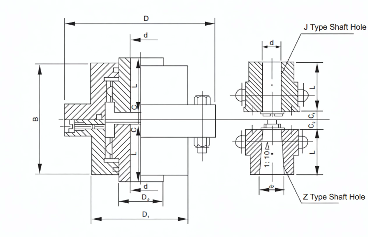
CL1 – CL16 Main Specifications
| Size | Nominal Torque Tn (N·m) |
Max Speed (rpm) |
Bore Range d (mm) |
Y bore length L range (mm) |
Outer Dia D (mm) |
CL Length B (mm) |
CLZ Length B1 (mm) |
Angular Tolerance |
CL Weight (kg approx) |
|---|---|---|---|---|---|---|---|---|---|
| CL1 | 40 | 4750 | 10–16 | 25–32 | 80 | 60 | 90 | 1.5 deg | 1.2 |
| CL2 | 63 | 4750 | 10–22 | 25–52 | 100 | 72 | 110 | 1.5 deg | 2 |
| CL3 | 100 | 4000 | 12–28 | 25–60 | 120 | 84 | 125 | 1.5 deg | 3.5 |
| CL4 | 160 | 3150 | 16–35 | 32–82 | 145 | 100 | 148 | 1.5 deg | 5.5 |
| CL5 | 250 | 2800 | 20–45 | 42–112 | 175 | 120 | 175 | 1.5 deg | 9 |
| CL6 | 400 | 2500 | 25–55 | 52–142 | 210 | 140 | 205 | 1.5 deg | 16 |
| CL7 | 630 | 2240 | 32–65 | 60–172 | 250 | 165 | 240 | 1.5 deg | 26 |
| CL8 | 1000 | 2000 | 40–80 | 84–212 | 295 | 190 | 280 | 1.5 deg | 42 |
| CL9 | 1600 | 1800 | 50–95 | 107–252 | 350 | 225 | 330 | 1.5 deg | 65 |
| CL10 | 2500 | 1600 | 60–110 | 107–302 | 415 | 265 | 390 | 1.5 deg | 105 |
| CL11 | 4000 | 1400 | 75–130 | 132–352 | 485 | 310 | 455 | 1.5 deg | 165 |
| CL12 | 6300 | 1250 | 90–160 | 172–410 | 570 | 365 | 535 | 1.5 deg | 260 |
| CL13 | 10000 | 1120 | 110–200 | 212–470 | 670 | 430 | 630 | 1.5 deg | 415 |
| CL14 | 16000 | 1000 | 130–240 | 252–550 | 790 | 500 | 735 | 1.5 deg | 650 |
| CL15 | 25000 | 900 | 160–280 | 302–650 | 930 | 585 | 860 | 1.5 deg | 1030 |
| CL16 | 40000 | 800 | 190–320 | 352–750 | 1090 | 680 | 1000 | 1.5 deg | 1600 |
Note: Weight values are approximate, based on maximum bore Y type. Bore ranges shown are for Y type; J1 type bores use the same bore diameter range with increased engagement length L. Z taper bores (1:10) are available up to the maximum bore diameter shown. CLZ B1 length values indicate the extended sleeve variant. All torque ratings are nominal (Tn); multiply by 1.25 for peak torque check in the selection calculation.
Custom Bore, Non-Standard Engagement Length, and CL/CLZ Available Together
Any bore diameter within the range for the chosen CL size can be machined to your shaft drawing — including metric IEC motor shaft sizes (14, 19, 24, 28, 38, 42, 48, 55, 60, 65, 75, 80 mm and above). Both CL and CLZ sleeves can be ordered for the same pair of inner hubs, allowing future sleeve exchange if the shaft gap changes. Send your shaft drawing or motor frame size for a confirmed bore specification.
Industries & Applications in Australia
The CL type gear coupling is the most versatile coupling in the industrial drive engineer's toolkit — it covers everything from small pump and fan drives to large conveyor and compressor drives, across the full range of Australian industries. Its crowned tooth design, economical cost, and wide bore range make it the default choice whenever a flexible but torque-rigid coupling is needed and the application does not require the specialised features of the WG or DC series.
General Industrial Pump and Fan Drives
Equipment: Centrifugal process pumps (CL3–CL8), industrial fans and blowers (CL4–CL9), rotary positive displacement pumps, cooling tower fan drives, water treatment pump sets.
Pump and fan drives are the highest-volume application for CL couplings across Australian water utilities, food and beverage processing, chemical plants, and HVAC installations. The most common installation problem on pump and fan drives is foundation settlement misalignment — where the motor base and pump base settle at different rates over time, generating angular and radial misalignment that destroys straight-tooth couplings within weeks. The CL's crowned tooth accommodates this settlement misalignment continuously without generating edge stress, extending coupling life significantly beyond the alternative rigid or straight-tooth designs. Explore our full range of industrial gear couplings for Australian applications.
Mining Conveyor and Auxiliary Drives
Equipment: Belt conveyor head drives (CL8–CL14), mine ventilation fan drives (CL6–CL11), ore feed conveyor drives, aggregate conveyor drives, quarry plant equipment drives across WA, QLD, and NSW.
Australian mining conveyor drives face a constant challenge: gearbox and motor foundations in mining environments settle unevenly due to vibration, loose fill, and thermal cycling — generating shaft misalignment that compounds with each conveyor startup shock. The CL coupling absorbs both the startup shock loads (peak torque 2–3x running torque on loaded belt starts) and the foundation settlement misalignment simultaneously, protecting gearbox input bearings from the combined edge loading and shock fatigue that destroys straight-tooth alternatives. For the heaviest conveyor head drives (CL12–CL16), GBC offers CL couplings with carburised and case-hardened teeth to HRC 58–62 for maximum shock resistance.
Compressor and Blower Drives
Equipment: Screw and reciprocating air compressor drives (CL5–CL10), industrial gas compressor drives, blower and rotary lobe drives, refrigeration compressor couplings.
Reciprocating and screw compressor drives in Australian manufacturing and process facilities generate high-frequency torque pulses superimposed on the steady running torque. These pulses, combined with the thermal shaft growth during heat-soak of a compressor package, create an operating environment that requires both good shock absorption and reliable axial displacement capability. The CL's crowned tooth absorbs torque pulses without elastomer degradation (unlike jaw couplings), and its axial sliding clearance accommodates shaft thermal growth of up to 4 mm without generating thrust forces at motor or compressor bearings.
Mixer, Agitator, and Extruder Drives
Equipment: Industrial process mixer drives (CL6–CL12), rubber and plastic extruder coupling sets, food processing agitator drives, chemical reactor stirrer drives, kneader drives.
Mixer and extruder drives require a coupling that tolerates high cyclic torque variation — from light unloaded torque to full material resistance torque — without fatigue failure. The CL's gear mesh transmits this variable load cycle without elastomer fatigue, and its crowned tooth absorbs the occasional shock load when a mixer encounters a foreign body in the material without the catastrophic failure that would occur with a disc pack coupling. The CLZ variant is particularly useful on extruder drives where the motor-to-gearbox shaft gap is fixed by the extruder barrel structure.
Replacement and Maintenance Couplings — OEM Machine Retrofits
Equipment: Any machine imported from China, Taiwan, or Korea that uses a GB/T5843 CL coupling as original equipment, factory maintenance replacement couplings, Australian-built machines that specify to GB standards.
A significant portion of the industrial machinery installed in Australian factories since 2000 uses CL couplings as original equipment — specified by the Chinese or Taiwanese machine builder to GB/T5843. When these couplings require replacement, matching the GB/T5843 size (CL1 through CL16) and bore to the original specification allows direct substitution without shaft modification. GBC's CL replacement couplings match original equipment dimensions precisely and are available with same-day quote from stock bore ranges. Contact us with the CL size marked on your existing coupling.
Technical Advantages — Why Crowned Tooth Outperforms Straight Tooth
Higher Misalignment Tolerance — Critical for Australian Mining and Process Plant
In Australian mining, quarrying, and heavy process environments, shaft misalignment is not a temporary installation error — it is a continuous operating condition caused by ground movement, structural settling, thermal cycling, and variable loading. Studies of Australian mining conveyor drives show that motor-to-gearbox shaft misalignment varies by 0.2–0.8 degrees over a typical production shift as the plant structure responds to ambient temperature changes and loading variations. A straight-tooth coupling generates tooth edge loading proportional to this misalignment, creating stress cycles that fatigue the tooth flanks within 6–18 months. The CL's crowned tooth maintains uniform contact ellipse distribution regardless of misalignment state — there is no increase in tooth stress from misalignment up to 1.5 degrees, eliminating misalignment-induced tooth fatigue entirely.
Longer Service Life Under Shock Loads
Every industrial drive experiences shock loads — conveyor belt starts under load, compressor pressure build-up, mixer blade contact with oversize material, and pump cavitation events all generate torque spikes of 2–4x running torque. The CL's crowned teeth distribute these peaks as Hertzian contact ellipses at the tooth flank centre, with no edge stress concentration. This means the tooth surface fatigue limit governs service life — not the edge stress limit that governs straight-tooth performance under shock. In documented comparisons across Australian industrial drives, CL crowned tooth couplings achieve 3–5x the tooth service life of equivalent straight-tooth couplings under the same combined misalignment and shock loading conditions.
Reduced Bearing Loads — Protecting Motor and Gearbox Bearings
When a coupling transmits misalignment-induced bending moments to the shaft, those moments are reacted at the nearest shaft bearings as additional radial loads. In a straight-tooth coupling at 0.5 degree misalignment, this additional bearing load can exceed 30–50% of the normal operating radial load — dramatically reducing bearing L10 life. The CL's crowned tooth self-centring mechanism minimises transmitted bending moments at all misalignment values within the rated tolerance, keeping bearing loads close to the design point values. For Australian plant engineers calculating bearing replacement intervals on motor and gearbox bearings, specifying CL type couplings consistently produces bearing lives 20–40% longer than straight-tooth alternatives in the same application.
Lower Maintenance Frequency — Less Downtime Per Year
CL couplings require periodic re-lubrication (every 6–12 months) and periodic tooth wear inspection — but no consumable elastomers, no disc pack replacement, and no wear-induced misalignment that progressively degrades drive train alignment as with jaw couplings. The typical CL coupling replacement interval in a well-lubricated, correctly aligned installation is 5–10 years in standard industrial duty, compared to 1–3 years for jaw couplings and 2–5 years for disc pack couplings in the same duty. For Australian maintenance planners managing annual maintenance budgets, the longer replacement interval and lower consumable cost of the CL coupling translate directly to reduced maintenance spend per drive per year.
Suitable for High-Speed Applications — Up to 4750 RPM
CL1 through CL4 are rated to 4750 and 3150 RPM respectively — fully compatible with 2-pole IEC motors on Australian 50 Hz supplies (2960 RPM nominal speed). For applications at speeds above 2500 RPM, the coupling must be balanced to ISO 1940/1 Grade G6.3 or better, and the bore fit should be H7/k6 to ensure concentricity. For CL5 through CL8 on 4-pole motor drives (1480 RPM nominal), no special balancing is required at standard bore fit tolerances. The CL's metal-only construction (no elastomers) means there is no speed-dependent degradation from centrifugal loading on flexible elements, unlike jaw couplings at high speed.
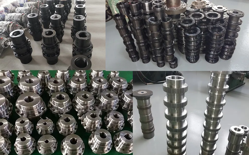
Manufacturing & Quality Assurance
Manufacturing Process
CL inner hubs are manufactured from forged steel blanks — 45# carbon steel for smaller sizes (CL1–CL8) and 42CrMo4 alloy steel for larger sizes (CL9–CL16). The outer sleeves are machined from seamless alloy steel tube or forged rings depending on size. Crowned teeth are CNC hobbed to GB/T10095 Class 8 accuracy (equivalent to DIN 3962 Class 8), with tooth profile measured on a gear testing instrument after hobbing to confirm crown height and profile accuracy. Tooth flanks are either induction hardened (CL1–CL10) or carburised and quench hardened (CL11–CL16) to HRC 50–58 surface hardness with HRC 28–35 core hardness, providing the combination of hard wear-resistant surface and tough shock-absorbing core that is essential for the combined misalignment and shock loading duty of industrial drive couplings.
All bores are finish-machined after heat treatment to H7 tolerance using CNC boring or grinding. Keyways are broached to JS9 tolerance. Z type taper bores (1:10) are verified with taper plug gauges and blue contact checks for minimum 75% contact before acceptance. The outer sleeve internal gear teeth are hobbed before any heat treatment to maintain dimensional accuracy — the outer sleeve is normalised but not through-hardened, providing sufficient wear resistance while maintaining dimensional stability.
Quality Control Flow
Certifications
ISO 9001:2015 quality management certification covers the full CL/CLZ manufacturing process. CE marking is applicable to relevant export sizes. Products manufactured per GB/T5843. Every shipment includes material mill certificates with heat traceability, heat treatment records, Rockwell hardness test certificates, and dimensional inspection reports including bore tolerance and keyway position verification. For Australian plant engineering records, documentation is structured with AS/NZS-compatible material identification to facilitate local quality plan compliance.
Why Source Your CL Couplings from GBC?
GB/T5843 Standard Knowledge for Australian Buyers
Many Australian maintenance engineers receive size specifications directly from machine documentation in GB format (e.g. "CL8, bore 75 H7"). GBC's engineering team reads and interprets GB/T5843 specifications directly, confirms the correct hub and sleeve combination, and provides the bore specification in Australian format for cross-reference. We can match CL couplings to existing machines from Chinese, Taiwanese, or Korean OEM manufacturers without requiring the Australian buyer to interpret unfamiliar standards documentation.
15+ Years Exporting to Australia
GBC has supplied CL and CLZ couplings to Australian industrial buyers, maintenance contractors, and machine importers since 2010. We understand Australian packaging requirements (ISPM-15 timber packing), import documentation (HS codes, certificate of origin, material traceability), and the documentation expectations of Australian maintenance quality plans. Every shipment is documented for straightforward customs clearance.
English-Speaking Engineering Team
GBC's engineers discuss CL coupling selection in clear technical English — confirming size from transmitted torque and service factor, bore specification from shaft diameter and key engagement requirements, and CL vs CLZ sleeve selection from shaft gap. For Australian plant engineers and maintenance supervisors who need a quick technical assessment before placing an order, our team responds within hours, not days.
From Single Replacement Units to Project Quantities
CL couplings are available from a single replacement unit (urgent maintenance replacement for a failed coupling) to full project quantities for new-build plant with multiple drives. Standard bore combinations from CL1 to CL12 are held in stock. Custom bore dimensions and CL13–CL16 ship within 10–15 working days. For project quantities of 20 or more identical units, contact our team for project pricing and scheduling.
Hub and Sleeve Sold Separately
CL inner hubs and outer sleeves are available as individual components, not only as matched pairs. This allows you to replace a worn outer sleeve without replacing the shaft-mounted hubs, or to order a CLZ sleeve for an existing CL hub pair when the shaft gap changes during a plant modification. Component pricing is available on request for both standard and custom bore specifications. Request component pricing here.
Full Gear Coupling Range — One Supplier
GBC supplies CL and CLZ alongside the WG, WGP, WGC, WGZ, WGT, DC, and other coupling families. Projects mixing CL couplings on standard drives with WG or WGT on specialised drives are served by one engineering team, one documentation set, and one shipping event — simplifying procurement for plant projects with multiple coupling specifications.
Application Case Studies
Case 1: Food Processing Conveyor Drive Replacement — Queensland
Customer Profile: A Queensland food processing facility operating 24 belt conveyor drives rated 11–37 kW on a chilled product handling line, with couplings exposed to frequent cleaning wash-down and high humidity. Original couplings were jaw type elastomeric, averaging 14 months replacement interval due to elastomer degradation from the wash-down chemicals and low-temperature operating environment.
Challenge: Jaw coupling elastomers on the product handling conveyors were degrading within 12–16 months from repeated wash-down with alkaline cleaning solution at 60 degrees Celsius, creating coupling backlash that caused product registration errors on the line. The maintenance manager needed a coupling with no elastomers, tolerance of wet and chemical environments, and equivalent shock absorption capability.
Solution: We supplied 24x CL couplings in sizes CL5 to CL8 (250–1000 N·m) with food-grade grease pre-fill and stainless steel hardware for the fill port assembly. The CL's gear mesh requires no elastomers and is unaffected by wash-down chemicals at the tooth mesh zone, which is sealed from external contamination by the sleeve end seals.
Result: 31 months since installation with zero coupling replacements across all 24 drives. The product registration errors caused by jaw coupling backlash were eliminated from the first installation. The maintenance manager reports the CL re-lubrication interval is 12 months, versus 8 months for the previous jaw couplings — and the CL re-lubrication takes 5 minutes per coupling versus 25 minutes for jaw coupling elastomer inspection and replacement. Annual coupling maintenance cost for the 24 drives reduced by approximately AUD $36,000.
Case 2: Chinese-Built Packaging Machine Replacement Couplings — Victoria
Customer Profile: A Victorian packaging operation with 8 blister pack machines sourced from a Chinese OEM, each with 3 CL couplings per machine (CL4, CL5, and CL6 in different drive positions) requiring replacement after 4 years of production operation.
Challenge: The maintenance team had the original machine documentation in Chinese showing coupling sizes as "CL4, CL5, CL6 per GB/T5843" but no bore dimensions. Three local coupling suppliers had been unable to cross-reference the GB/T5843 standard and had quoted incorrect bore sizes that would not have fitted the existing shafts. The maintenance manager needed a supplier who understood the GB standard directly.
Solution: We measured the worn coupling bores from the customer's photos and specifications, confirmed the CL4 bore at 28 mm, CL5 bore at 35 mm, and CL6 bore at 45 mm from the machine shaft drawings, and supplied 24x replacement couplings (8 machines x 3 sizes) with confirmed bore specifications and keyway dimensions matched to the original machine shafts.
Result: All 24 replacement couplings installed correctly on first attempt — zero rework or remachining. The maintenance manager has since placed repeat orders for the same coupling combinations at each 4-year machine service interval. Availability of manufacturer-direct CL replacement couplings at correct GB/T5843 specifications eliminated the 3–4 week local sourcing delay that had previously caused extended machine downtime on this coupling type.
Case 3: Mine Ventilation Fan Drive Upgrade — Western Australia
Customer Profile: A gold mine in the Goldfields region of Western Australia operating 6 underground ventilation fans rated 75 kW each, with motor-to-fan shaft spans requiring CLZ configuration due to fan bearing housing standout.
Challenge: The existing fan drives used flexible disc coupling sets that were fatigue-failing within 18 months under the combined shock loading of fan blade imbalance events and the frequent starts and stops of the underground ventilation scheduling. Each disc coupling failure required full mine ventilation system switchover, triggering a mandatory production hold until the failed fan was back online — typically 6–8 hours. The mine's electrical engineer needed a coupling with much higher shock tolerance than the disc pack design.
Solution: We supplied 6x CL9 CLZ couplings (1600 N·m, d=65 mm, with CLZ extended sleeve to match the existing fan bearing housing standout of 280 mm). The CL9's crowned tooth shock tolerance was confirmed by calculation to handle the 3x rated torque peaks from fan blade imbalance events without tooth edge fatigue. CL9's carburised teeth provided the required surface hardness for the cyclic load duty.
Result: Zero coupling failures across all 6 fans in 30 months since installation — versus 2 failures per fan per 18-month period with the previous disc couplings. At an estimated 8-hour production hold per failure event and 6 fans over 30 months (10 expected failures avoided), the CL upgrade prevented approximately 80 hours of ventilation-related production delays. At the mine's estimated AUD $45,000 per hour production cost, the saving exceeded AUD $3.6 million over the 30-month comparison period.
Frequently Asked Questions
What is a CL type gear coupling?
The CL type gear coupling is a crowned tooth (drum shape) flexible coupling per GB/T5843. It consists of two inner hubs with external crowned teeth and a connecting outer sleeve with internal straight teeth. The crowned tooth geometry transmits torque while accommodating angular, radial, and axial shaft misalignment without edge loading. CL covers 16 sizes from CL1 (40 N·m, 4750 rpm) to CL16 (40,000 N·m, 800 rpm). CLZ is the extended sleeve variant for wider shaft spans.
How do I select the correct CL size for my drive?
The design torque Td = T x Ks, where T is the nominal running torque (calculated from motor power and speed: T = 9550 x P/n) and Ks is the service factor (1.25–2.5 depending on drive type and duty class). Select the CL size where the nominal torque Tn is greater than or equal to Td. For shock loading applications, multiply by a shock factor of 1.5–2.5 before comparison. Our engineering team performs this calculation for every order as a standard service — provide motor power, speed, and application type for a confirmed size recommendation.
What is the difference between CL and CLZ?
CL and CLZ use identical inner hubs for the same size number, with the same torque rating, bore range, and speed limit. The only difference is the outer sleeve length — CLZ has an extended sleeve that spans a wider shaft gap. Choose CL for standard close-coupled drives; choose CLZ when the motor and machine shaft ends are further apart than the CL sleeve can bridge in its standard B dimension. The inner hubs of CL and CLZ are interchangeable within the same size number.
How do I lubricate a CL type gear coupling?
Re-lubricate through the fill port at the mid-span of the outer sleeve at 6–12 month intervals using lithium complex grease (NLGI Grade 2) or EP gear oil. Inject grease until it emerges from the vent port or the opposite fill hole, confirming both tooth mesh zones are filled. For CL1 to CL5, the total grease quantity per re-lubrication is approximately 10–80 grams. For CL10 to CL16, total grease quantity is approximately 500–2000 grams per fill. Purge old grease from the vent port before re-filling to avoid over-pressure in the sleeve cavity.
Can I replace the outer sleeve without removing the inner hubs from the shafts?
Yes, on CL couplings where the shafts can be moved axially by the sleeve length B (or B1 for CLZ). The standard CL disassembly procedure is to slide one shaft axially to create clearance, slide the sleeve off the first hub, and then return the shaft to position. For CLZ couplings with extended sleeves, the axial shaft movement required is reduced. On drives where axial shaft movement is not possible (e.g. on bearing preloaded shafts), sleeve replacement requires hub removal from at least one shaft — contact our team for advice on specific installations.
Are CL couplings directly interchangeable with GICL type couplings?
CL per GB/T5843 and GICL per JB/T8854.3 are both crowned tooth gear couplings and share similar application intent, but their dimensional geometry is different — they are not directly interchangeable without checking bore, outer diameter, and coupling length. The torque ratings at the same size number are approximately similar but not identical between the two standards. If you need to substitute CL for GICL or vice versa, provide both coupling's size numbers and bore data to our team for a confirmed dimensional compatibility check before ordering.
Get Your CL or CLZ Coupling Quoted Today
Send us your coupling size (CL1–CL16), bore diameter, keyway dimensions, and CL or CLZ sleeve requirement. If you only have the motor power and speed, our engineering team will select the correct size for you. Factory-direct quotation within 24 hours — with full bore specification confirmation and documentation package.
|
GB/T5843 standard expertise
|
sales@australia-drive.com
GBC — Factory-direct CL and CLZ crowned tooth gear couplings per GB/T5843 for Australian industrial maintenance, replacement, and new-build applications since 2010.
CL type crowned tooth gear coupling per GB/T5843. 16 sizes (CL1–CL16), 40 N·m to 40,000 N·m, up to 4750 RPM. CL compact and CLZ extended sleeve variants. Y, J1, Z bores. Suits pump, fan, conveyor, compressor, and general industrial drives. Custom bore to drawing. Factory direct to Australia.