JM Type Single Diaphragm Coupling with Intermediate Shaft
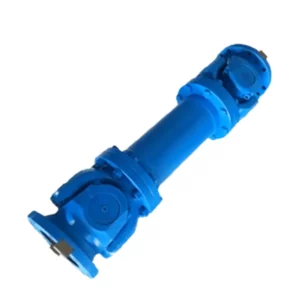
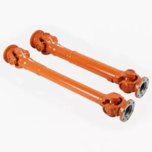
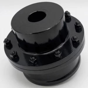
The JM Type Single Diaphragm Coupling with Intermediate Shaft (rod type) bridges two machine shaft ends through a rigid intermediate tube with a stainless steel diaphragm pack at each end. Available in 30 sizes from JM1 (40 N·m) to JM30 (180,000 N·m) at speeds up to 10,700 rpm — the standard solution for long shaft spans on pumps, fans, paper machines, and drives where equipment must remain in place during maintenance without shaft uncoupling.
What Is a JM Type Single Diaphragm Coupling with Intermediate Shaft?
The JM type single diaphragm coupling with intermediate shaft — also called a rod-type or spacer-type diaphragm coupling — addresses the practical problem that arises whenever two machine shaft ends cannot be brought close enough together for a compact coupling: pumps with back-pullout access requirements, fans with overhung impellers, turbine-to-gearbox drives, and paper machine section drives all fall into this category.
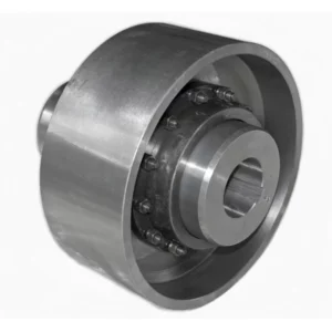
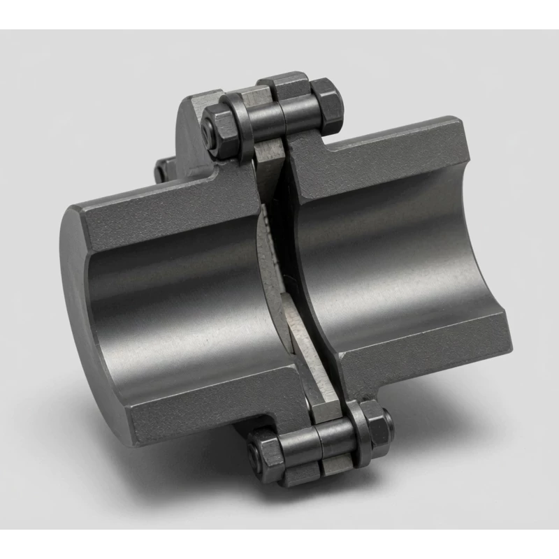
The JM coupling consists of two standard single-diaphragm pack assemblies — one at each end of a rigid intermediate shaft tube. Each diaphragm pack independently compensates for angular and axial misalignment at its respective shaft interface, giving the JM type approximately twice the total misalignment accommodation of a compact DJM coupling. The intermediate shaft transmits torque in pure torsion between the two joints; because both ends are flexible, radial forces on the shaft bearings from misalignment are minimal even over large shaft spans.
JM vs JMJ — Choosing the Right Rod Type
| Feature | JM (Single pack each end) | JMJ (Double pack each end) |
|---|---|---|
| Packs per end | 1 | 2 |
| Axial compensation | Standard | ~Double |
| Angular compensation | 1° per end | 2° per end |
| Direct radial offset | Via angular flex | Direct per end |
| Hub OD (D1) | Smaller | Larger |
| Best for | Well-aligned long spans | Multi-axis misalignment; thermal offset |
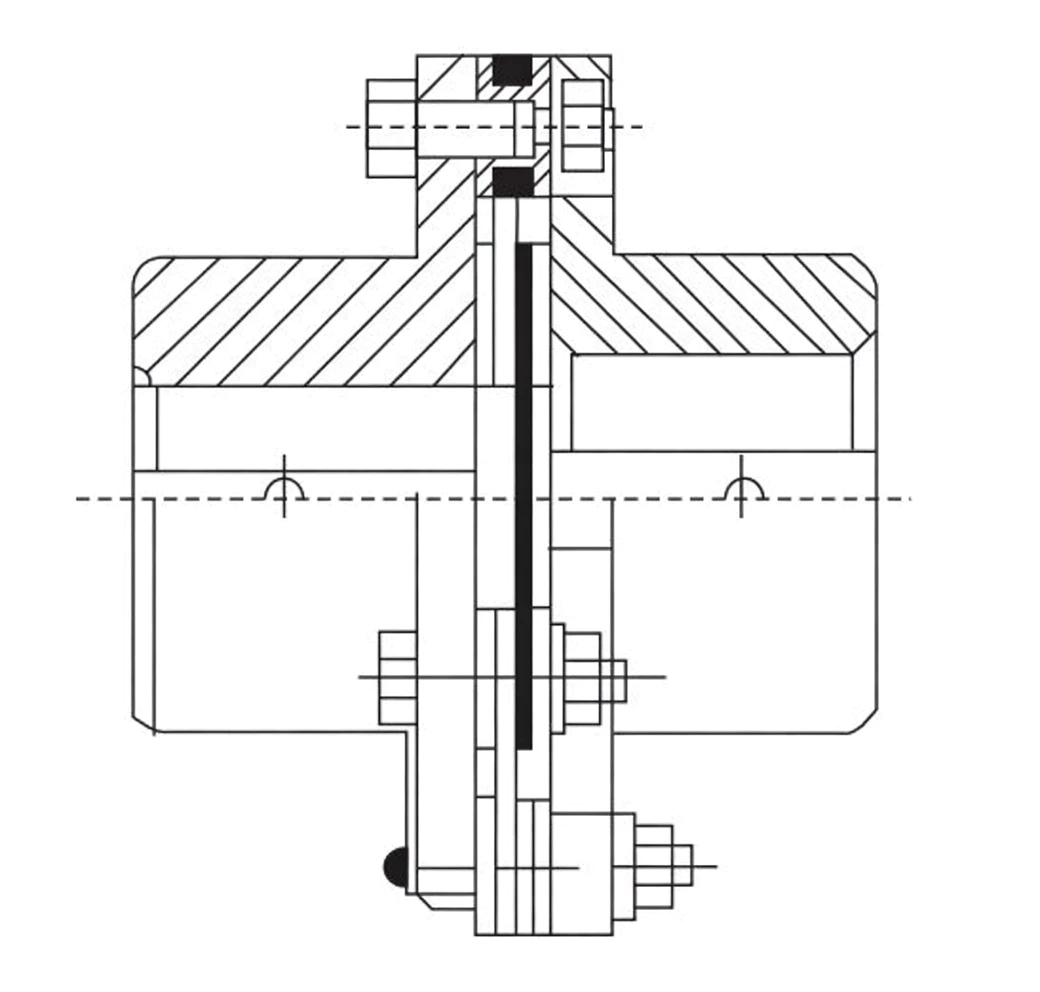
JM Coupling Specifications and Dimensions
Materials
Diaphragm packs (two per coupling): stainless steel sheet. Hubs: alloy steel. Intermediate shaft tube: precision-drawn alloy steel tube. Mass and inertia calculated at recommended L (shaft length); actual values proportional to L. Imperial bore and custom shaft lengths available on request.
Ordering Mark Example
→ Size JM10 | Drive: J1-type bore A-keyway d=70 mm L=107 mm | Driven: Y-type bore A-keyway d=80 mm L=172 mm
Complete Parameter Table — JM1 to JM30
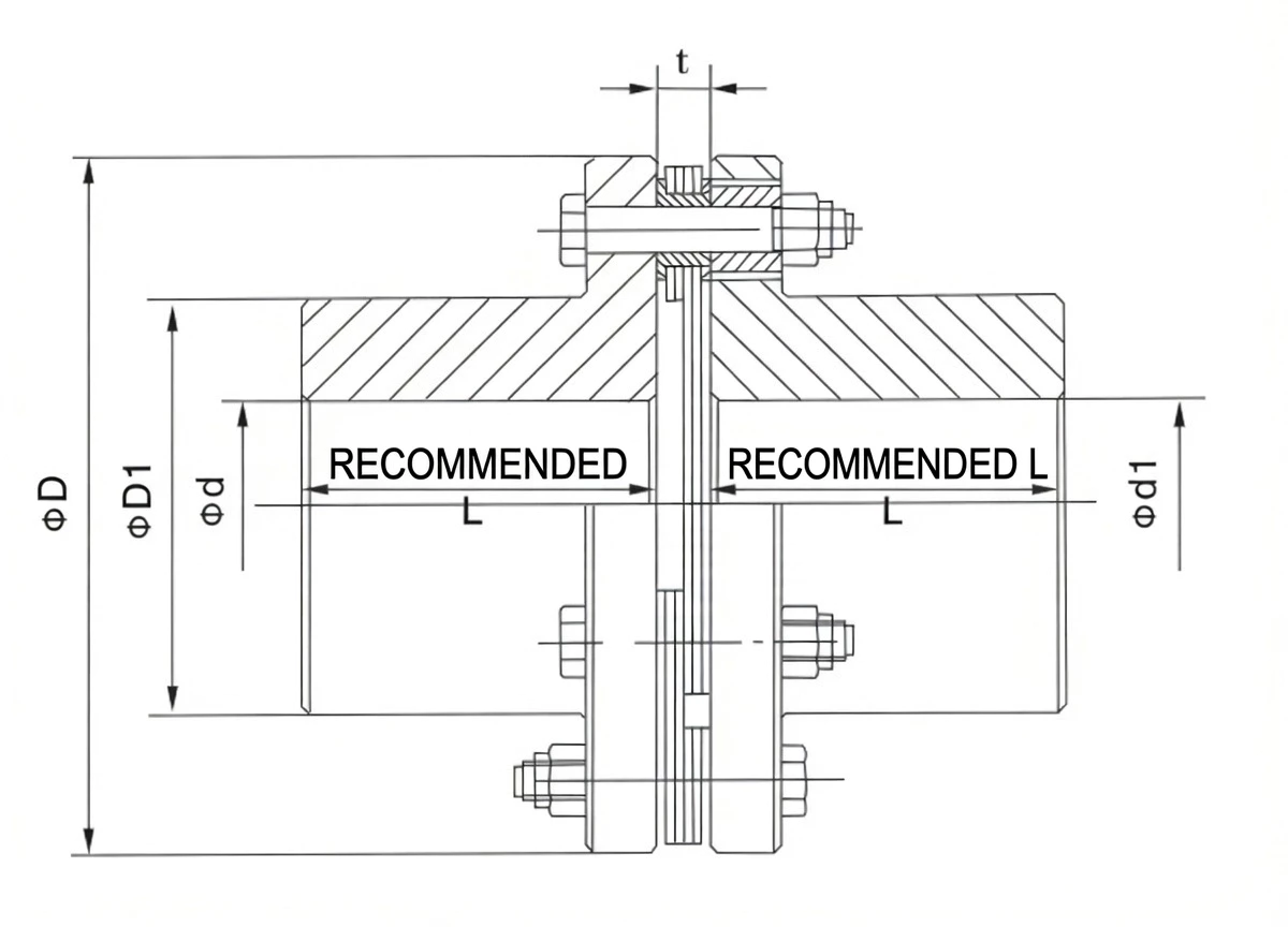
t = diaphragm pack thickness (mm). D = flange OD (mm). D1 = hub OD (mm). Torsional rigidity in N·m/rad ×10⁶. Mass and inertia calculated at recommended L. Angular compensation: 1° per end for all sizes.
| Type | Nom. Torque N·m | Inst. Torque N·m | Max Speed rpm | Bore d mm | L rec. mm | D mm | D1 mm | t mm | Torsional Stiffness N·m/rad ×10⁶ | Mass kg | Inertia Kg·m² |
|---|---|---|---|---|---|---|---|---|---|---|---|
| JM1 | 40 | 63 | 10,700 | 14 / 16,18,19 / 20,22,24 / 25,28 | 35 | 80 | 39 | 8±0.2 | 0.37 | 0.9 | 0.0005 |
| JM2 | 63 | 100 | 9,300 | 20,22,24 / 25,28 / 30,32,35,38 | 40 | 92 | 53 | 8±0.2 | 0.45 | 1.4 | 0.0011 |
| JM3 | 100 | 200 | 8,400 | 25,28 / 30,32,35,38 / 40,42,45 | 45 | 102 | 63 | 8±0.2 | 0.56 | 2.1 | 0.002 |
| JM4 | 250 | 400 | 6,700 | 30,32,35,38 / 40,42,45,48,50,55 | 55 | 128 | 77 | — | 0.81 | 4.2 | 0.006 |
| JM5 | 500 | 800 | 5,900 | 35,38 / 40,42,45,48,50,55,56 / 60,63,65 | 65 | 145 | 91 | 11±0.3 | 1.1 | 6.4 | 0.012 |
| JM6 | 800 | 1,250 | 5,100 | 40,42,45,48,50,55,56 / 60,63,65,70,71,75 | 75 | 168 | 105 | 14±0.3 | 1.42 | 9.6 | 0.024 |
| JM7 | 1,000 | 2,000 | 4,750 | 45,48,50,55,56 / 60,63,65,70,71,75 / 80 | 80 | 180 | 112 | 15±0.4 | 1.9 | 12.5 | 0.0365 |
| JM8 | 1,600 | 3,150 | 4,300 | 50,55,56 / 60,63,65,70,71,75 / 80,85 | 80 | 200 | 120 | 15±0.4 | 2.35 | 15.5 | 0.057 |
| JM9 | 2,500 | 4,000 | 4,200 | 55,56 / 60,63,65,70,71,75 / 80,85 | 80 | 205 | 120 | 20±0.4 | 2.7 | 16.5 | 0.065 |
| JM10 | 3,150 | 5,000 | 4,000 | 55,56 / 60,63,65,70,71,75 / 80,85,90 | 90 | 215 | 128 | 20±0.4 | 3.02 | 19.5 | 0.083 |
| JM11 | 4,000 | 6,300 | 3,650 | 60,63,65,70,71,75 / 80,85,90,95 | 100 | 235 | 132 | — | 3.46 | 25 | 0.131 |
| JM12 | 5,000 | 8,000 | 3,400 | 60,63,65,70,71,75 / 80,85,90,95 / 100 | 100 | 250 | 145 | 23±0.5 | 3.67 | 30 | 0.174 |
| JM13 | 6,300 | 10,000 | 3,200 | 63,65,70,71,75 / 80,85,90,95 / 100,110 | 110 | 270 | 155 | — | 5.2 | 36 | 0.239 |
| JM14 | 8,000 | 12,500 | 2,850 | 65,70,71,75 / 80,85,91,95 / 100,110 | 115 | 300 | 162 | 27±0.6 | 7.8 | 45 | 0.38 |
| JM15 | 10,000 | 16,000 | 2,700 | 70,71,75 / 80,85,90,95 / 100,110,120,125 | 125 | 320 | 176 | 27±0.6 | 8.43 | 55 | 0.5 |
| JM16 | 12,500 | 20,000 | 2,450 | 75 / 80,85,90,95 / 100,110,120,125 / 130 | 140 | 350 | 186 | — | 10.23 | 75 | 0.85 |
| JM17 | 16,000 | 25,000 | 2,300 | 80,85,90,95 / 100,110,120,125 / 130,140 | 145 | 370 | 203 | 32±0.7 | 10.97 | 85 | 1.1 |
| JM18 | 20,000 | 31,500 | 2,150 | 90,95 / 100,110,120,125 / 130,140,150 / 160 | 165 | 400 | 230 | — | 13.07 | 115 | 1.65 |
| JM19 | 25,000 | 40,000 | 1,950 | 100,110,120,125 / 130,140,150 / 160,170 | 175 | 440 | 245 | 38±0.9 | 14.26 | 150 | 2.69 |
| JM20 | 31,500 | 50,000 | 1,850 | 110,120,125 / 130,140,150 / 160,170,180 | 185 | 460 | 260 | 38±0.9 | 22.13 | 170 | 3.28 |
| JM21 | 35,500 | 56,000 | 1,800 | 120,125 / 130,140,150 / 160,170,180 / 190,200 | 200 | 480 | 280 | 38±0.9 | 23.7 | 200 | 4.28 |
| JM22 | 40,000 | 63,000 | 1,700 | 130,140,150 / 160,170,180 / 190,200 | 210 | 500 | 295 | — | 24.6 | 230 | 5.18 |
| JM23 | 50,000 | 80,000 | 1,600 | 140,150 / 160,170,180 / 190,200,220 | 220 | 540 | 310 | 44±1 | 29.71 | 275 | 7.7 |
| JM24 | 63,000 | 100,000 | 1,450 | 150 / 160,170,180 / 190,200,220 / 240 | 240 | 600 | 335 | 50±1.2 | 32.64 | 380 | 9.3 |
| JM25 | 80,000 | 125,000 | 1,400 | 160,170,180 / 190,200,220 / 240,260 | 255 | 620 | 350 | 50±1.2 | 37.69 | 410 | 15.3 |
| JM26 | 90,000 | 140,000 | 1,300 | 180 / 190,200,220 / 240,250,260 | 275 | 660 | 385 | 50±1.2 | 50.43 | 510 | 20.9 |
| JM27 | 112,000 | 180,000 | 1,200 | 190,200,220 / 240,250,260 / 280 | 295 | 720 | 410 | — | 71.51 | 620 | 32.4 |
| JM28 | 140,000 | 200,000 | 1,150 | 220 / 240,250,260 / 280,300 | 300 | 740 | 420 | 60±1.4 | 93.37 | 680 | 36 |
| JM29 | 160,000 | 224,000 | 1,100 | 240,250,260 / 280,300,320 | 320 | 770 | 450 | 60±1.4 | 114.53 | 780 | 43.9 |
| JM30 | 180,000 | 280,000 | 1,050 | 250,260 / 280,300,320 / 340 | 350 | 820 | 490 | 60±1.4 | 130.76 | 950 | 60.5 |
Note: Mass and inertia are approximate values calculated at recommended L using cast steel. Actual values proportional to L. J1-type bore length L is shorter than Y-type. Custom intermediate shaft lengths and imperial bores available on request.
How to Select a JM Coupling
Design Torque Formula
Intermediate Shaft Length Selection
The intermediate shaft length L is determined by the required shaft-end gap. Standard L values for each size are listed in the table; custom lengths are available. For L above the recommended value, verify lateral critical speed is well above operating speed — contact GBC engineering with the full drive arrangement for a rotordynamic check on shafts exceeding 1.5 m.
- Calculate TC: Apply service factor K; select size where Tn ≥ TC.
- Confirm bore range: Both shaft diameters must fall within the listed bore range for the selected size.
- Choose intermediate shaft length: Standard or custom L to suit the shaft-to-shaft gap. Check rotordynamic limit for L > 1.5 m.
- Select hole type: J1 (short cylindrical) or Y (long cylindrical, standard keyway). J1 is more compact; Y is standard.
- Verify speed: Operating speed must be below the rated maximum and well below the calculated lateral critical speed of the intermediate shaft.
Related Diaphragm Coupling Types
9.8–8,100,000 N·m · No intermediate shaft · For close-coupled drives
Zero backlash hub connections · CNC, servo, heavy industrial · Compact
420–25,410 N·m · Integrated disc brake · Servo braked drives
40–180,000 N·m · Rod-type · Long shaft spans · 1° per end
63–180,000 N·m · Rod-type · Double pack each end · 2° per end · Radial compensation
For greater radial offset capacity on long shaft spans, the JMJ double-pack intermediate shaft coupling provides direct radial compensation at each joint.
Applications
API 610 and EN ISO 5199 centrifugal pumps require the pump casing to remain in its pipework during maintenance — the motor and bearing housing pull back axially. JM spacing allows this without disconnecting the pipework or disturbing the pump casing alignment. JM10–JM18 cover the typical range for these pump sizes.
Paper machine dryer section drives involve spans of 600–1,500 mm between the gearbox output shaft and the dryer shell journal. JM couplings bridge these spans while accommodating thermal expansion of the dryer shell (axial compensation) and the slight parallel offset between gearbox and dryer centrelines (angular compensation at each end).
Industrial fans with overhung impellers and gear-driven motor connections use JM couplings to span the distance between the gearbox output and the fan shaft journal. The intermediate shaft allows the motor and gearbox to remain in place while the fan is removed for impeller inspection and rebalancing.
Steam and gas turbine to generator direct-drive couplings use JM rod-type designs to span the gap between turbine coupling flange and generator coupling flange, accommodating the thermal growth differential between turbine and generator cases during warm-up and load changes.
Large auxiliary diesel alternator sets on ships use JM couplings where the engine crankshaft and alternator shaft are separated by a resilient mounting system. The intermediate shaft spans the anti-vibration mount gap while each diaphragm pack independently absorbs the residual angular misalignment at its end.
Top-entry agitator drives on large vessels often have a significant gap between the gearbox output shaft and the agitator shaft journal — sometimes 300–800 mm. JM bridges this gap while providing axial compensation for temperature-related shaft growth in the vessel, without transmitting side loads to the agitator lower bearing.
Installation and Maintenance
- Hub fitting: Fit both hubs to their shafts (press or heat, induction heater ≤120°C); torque setscrews.
- Alignment: Laser-align both shaft ends. The JM's two-joint flexibility accommodates combined misalignment at both ends simultaneously, but minimising initial misalignment maximises diaphragm service life.
- Intermediate shaft installation: Insert the intermediate tube between the two hub flanges. Confirm the tube length suits the shaft-to-shaft gap — the tube should fit with the recommended spacing without pre-loading either diaphragm pack axially.
- Diaphragm pack mounting: Fit both packs; torque all bolts per specification in three cross-pattern passes. Mismatched torque between the two ends produces unequal diaphragm stress.
- Shaft whip check: For intermediate shaft lengths above 1 m, calculate or measure the first lateral critical speed. Operating speed should not exceed 75% of the first lateral critical speed of the unsupported intermediate shaft.
| Symptom | Likely Cause | Action |
|---|---|---|
| High vibration at operating speed | Near lateral critical speed; imbalance | Calculate critical speed; balance intermediate shaft |
| Diaphragm cracking at one end | Misalignment at that joint exceeds 1° | Re-align that shaft end; replace diaphragm |
| Intermediate shaft whip | L too long for speed; operating at or near critical | Reduce speed or add intermediate bearing support |
| Fretting at hub bore | Inadequate hub fit; loose setscrew | Verify fit tolerance; re-torque setscrews |
Customer Case Studies
Australia — Water Authority, Large Pump Station
JM14 and JM15 on API 610 back-pullout pumps at a major coastal desalination plant. The intermediate shaft allows pump maintenance (seal and impeller replacement) without disturbing motor alignment or pipework. Operating continuously at 2,850 rpm in a corrosive environment — no coupling failures in three years, reduced scheduled maintenance time by 40%.
Rotating Equipment Engineer, Western Australia AU
★★★★★
Finland — Paper Mill
JM18 through JM22 on dryer section drives, intermediate shaft lengths 800–1,200 mm. Thermal expansion of the dryer shells (up to 6 mm axial) fully absorbed by the diaphragm packs with no bearing end-loading. The zero-lubrication design eliminated the grease contamination events we previously experienced on gear-type spacer couplings in our paper machine environment.
Mechanical Maintenance Superintendent, Kouvola FI
★★★★★
Canada — Hydropower Station
JM25 and JM26 on auxiliary pump drives in a run-of-river hydro station. Intermediate shaft lengths 950–1,050 mm spanning the gap between motor and pump across the equipment floor. Two years of commissioning operation — no alignment-related bearing failures, and the zero-maintenance diaphragm pack has not been inspected yet (scheduled for the four-year major overhaul).
Mechanical Engineer, British Columbia CA
★★★★☆
Germany — Industrial Fan OEM
JM10 through JM14 across our centrifugal fan drive range. We standardise JM intermediate shaft couplings to allow impeller removal without disturbing the gearbox. Dimensional drawings and material certificates are supplied with every batch — essential for our CE Declaration of Conformity documentation.
Mechanical Design Engineer, North Rhine-Westphalia DE
★★★★★
Frequently Asked Questions
▶ Why use an intermediate shaft rather than a compact coupling?
Compact couplings require both shaft ends to be within the coupling's own length of each other. When the gap between two machines is larger — due to equipment layout, back-pullout maintenance access, anti-vibration mounts, or shaft arrangement — a compact coupling cannot bridge the distance. The JM intermediate shaft type spans any required gap while providing the same zero-lubrication, high-speed diaphragm performance at each joint.
▶ Can the intermediate shaft length be specified to any dimension?
Custom lengths are available for any JM size. The parameter table lists recommended standard lengths for reference. For non-standard lengths, specify the required shaft-to-shaft gap when ordering and GBC will confirm the correct intermediate shaft length. For shafts above 1.5 m, a lateral critical speed calculation is performed — the operating speed must not exceed 75% of the first critical speed to avoid resonant whip.
▶ What is the difference between J1-type and Y-type bore holes?
J1-type (also called short cylindrical) has a shorter bore length — typically 60–70% of the Y-type equivalent — allowing a more compact hub section. Y-type has the standard long cylindrical bore with a full-length keyway. J1 is preferred where hub length is constrained; Y-type is the standard choice for most industrial applications. Both types accept the same range of bore diameters; the bore length L for each is listed in the parameter table.
▶ How is the JM coupling assembled in the field?
The coupling can be assembled without a press or special tools. Fit both hubs to their respective shafts (heating to ≤120°C for interference fits). Insert the intermediate shaft tube between the two hub flanges — confirm the gap equals the specified shaft-end-to-shaft-end distance. Fit the diaphragm packs at each end and torque the mounting bolts in a cross-pattern, three passes, to the specified values. Rotate by hand and confirm smooth operation before starting the machine.
▶ At what torque should the diaphragm pack bolts be tightened?
Bolt torque values are size-specific and are supplied with the coupling dimensional datasheet. As a guide, smaller sizes (JM1–JM5) use M5–M8 bolts torqued to 5–20 N·m; larger sizes (JM20–JM30) use M16–M24 bolts torqued to 200–550 N·m. Always use a calibrated torque wrench and tighten in three progressive cross-pattern passes to ensure uniform diaphragm compression. Over-torquing stresses the diaphragm at the bolt holes; under-torquing causes fretting.
Source JM Intermediate Shaft Couplings for Your Long-Span Drive
GBC supplies all 30 JM sizes with custom intermediate shaft lengths, imperial bore options, rotordynamic support for long shafts, and full dimensional documentation. Send us your motor power, speed, shaft-to-shaft gap, and bore diameters and our engineering team will confirm the correct size and shaft length within 24 hours.
The JM Type Single Diaphragm Coupling with Intermediate Shaft (rod type) bridges two machine shaft ends through a rigid intermediate tube with a stainless steel diaphragm pack at each end. Available in 30 sizes from JM1 (40 N·m) to JM30 (180,000 N·m) at speeds up to 10,700 rpm — the standard solution for long shaft spans on pumps, fans, paper machines, and drives where equipment must remain in place during maintenance without shaft uncoupling.