JSS Double Flange Grid Coupling
The JSS Double Flange Grid Coupling connects two flanged shafts through a serpentine spring mechanism with integrated connecting flanges on both sides. Spanning 19 sizes from 45 to 160,000 N·m with adjustable shaft gap distances, it is ideal for flange-connected equipment in chemical, marine, and heavy process industries.
JSS Double Flange Grid Coupling – Flanged Serpentine Spring Coupling for Process-Critical Connections
The JSS Double Flange Grid Coupling integrates two bolted connecting flanges into the grid coupling design, enabling direct flange-to-flange attachment between driving and driven equipment. This eliminates the need for keyway shaft connections on both ends, making the JSS the coupling of choice when equipment interfaces are defined by flange bolt circles rather than cylindrical shaft bores – a common configuration in marine propulsion, compressor trains, and large process pumps.
Covering 19 sizes from JSS1 (45 N·m) to JSS19 (160,000 N·m), the JSS double flange coupling features a variable two-shaft-end distance (L2) that accommodates different installation gaps between connected machines. The minimum and maximum L2 values for each size provide flexibility during plant layout and equipment alignment, while the serpentine spring core delivers the same 36% damping ratio and 99.47% efficiency as all grid coupling variants.
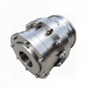
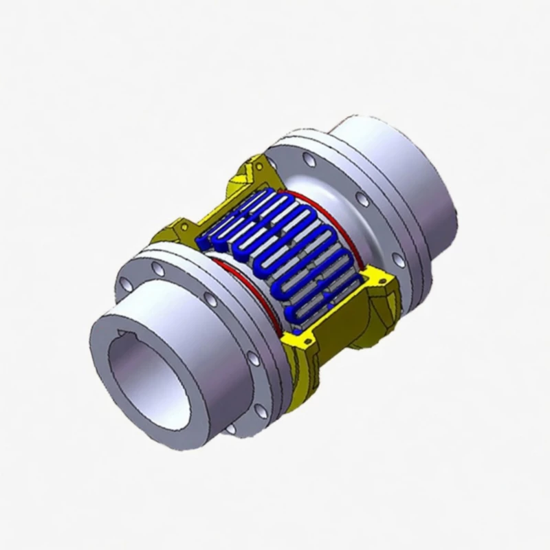
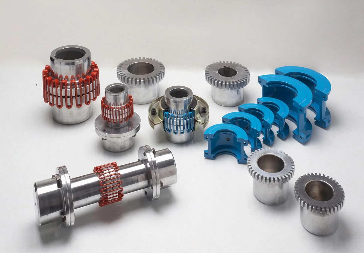
Fig. 1 – JSS Double Flange Grid Coupling product assembly
Design Advantages of Double Flange Configuration
Dual Flange Interface
Both coupling ends feature precision-drilled bolt flanges (D and D1 diameters), connecting directly to equipment flanges without keyway machining on the shaft.
Adjustable Shaft Gap (L2)
Each model specifies a minimum and maximum L2 distance, letting engineers accommodate varying equipment spacings from 89 mm to 575 mm across the range.
High Torque to 160,000 N·m
19 sizes cover the full industrial torque spectrum, from small instrumentation drives to heavy compressor and generator sets.
Torsional Vibration Control
The serpentine spring absorbs torsional harmonics from reciprocating compressors, diesel engines, and variable-frequency drives, preventing resonance propagation.
Bolted Flange Security
Precision bolt patterns on both D and D1 circles ensure concentricity and secure torque transfer even under severe misalignment or thermal expansion.
Field-Serviceable Spring
The spring element can be replaced without unbolting the flanges from the connected equipment – remove the shell, swap the spring, reassemble.
Structural Layout
The JSS coupling extends the standard grid coupling architecture with flanged hub ends:
Hub Halves with Flanges: Each hub integrates a precision-machined connecting flange. The flange bolt circle (D and D1) is sized per model to distribute torque evenly across the bolted connection. Shaft bores with keyways are available within each hub for dual retention.
Serpentine Spring: Identical spring element to the JS/JSB series, providing consistent damping and overload characteristics. Spring engagement occurs through the tooth profiles machined into both hub halves.
Shell and Seals: The enclosing shell retains lubricant and protects the spring from contamination. Two structural configurations are employed: JSS1–JSS13 use a compact housing, while JSS14–JSS19 use a reinforced housing with larger clearance gaps (C = 10 mm for JSS16–JSS17).
For applications requiring only a single flanged end, consider the JSD single flange grid coupling as an alternative.
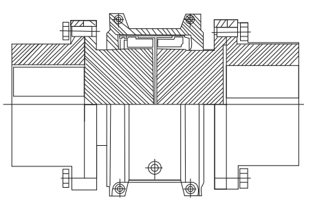
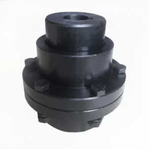
Fig. 2 – JSS Double Flange Grid Coupling cross-section and dimensional drawing
Technical Specifications – JSS Double Flange Grid Coupling
Full specifications for all 19 sizes. Shaft bore ranges shown as minimum to maximum available diameter. L2 columns show the adjustable two-shaft-end gap range.
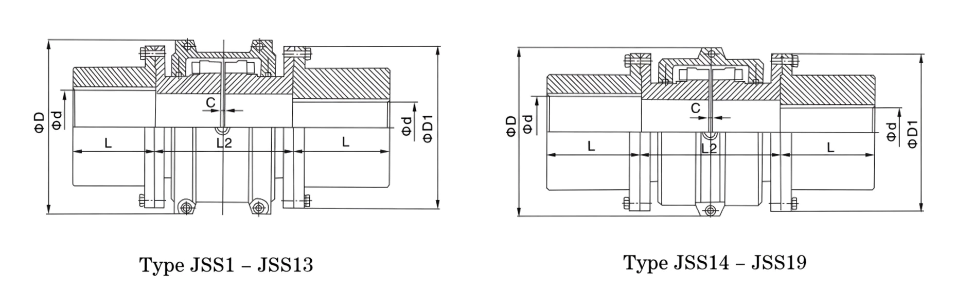
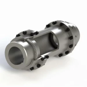
Fig. 3 – JSS Double Flange Grid Coupling complete dimensional reference
| Model | Nominal Torque Tn (N·m) |
Max Speed (rpm) |
Shaft Bore d Range (mm) |
Bore Length L (mm) |
L2 Min (mm) |
L2 Max (mm) |
D (mm) | D1 (mm) | C (mm) | Weight (kg) |
Lubricant (kg) |
|---|---|---|---|---|---|---|---|---|---|---|---|
| JSS1 | 45 | 3,600 | 18–35 | 35 | 89 | 203 | 97 | 86 | 5 | 3.86 | 0.027 |
| JSS2 | 140 | 3,600 | 22–42 | 42 | 89 | 203 | 106 | 94 | 5 | 5.27 | 0.041 |
| JSS3 | 224 | 3,600 | 25–56 | 54 | 89 | 216 | 114 | 112 | 5 | 8.44 | 0.054 |
| JSS4 | 400 | 3,600 | 32–65 | 60 | 111 | 216 | 135 | 125 | 5 | 12.53 | 0.068 |
| JSS5 | 630 | 3,600 | 40–80 | 73 | 127 | 300 | 148 | 144 | 5 | 19.61 | 0.086 |
| JSS6 | 900 | 3,600 | 48–85 | 80 | 127 | 300 | 159 | 152 | 5 | 24.56 | 0.135 |
| JSS7 | 1,800 | 3,600 | 55–95 | 89 | 127 | 184 | 190 | 178 | 6 | 39.4 | 0.173 |
| JSS8 | 3,150 | 3,600 | 65–110 | 102 | 127 | 184 | 211 | 209 | 6 | 60.38 | 0.254 |
| JSS9 | 5,600 | 2,440 | 75–130 | 90 | 203 | 406 | 251 | 250 | 6 | 98.97 | 0.427 |
| JSS10 | 8,000 | 2,250 | 80–150 | 104 | 210 | 406 | 270 | 276 | 6 | 137.58 | 0.508 |
| JSS11 | 12,500 | 2,025 | 90–170 | 120 | 246 | 406 | 308 | 319 | 6 | 196.58 | 0.735 |
| JSS12 | 18,000 | 1,800 | 110–190 | 135 | 257 | 406 | 346 | 346 | – | 259.69 | 0.908 |
| JSS13 | 25,000 | 1,650 | 120–200 | 152 | 267 | 406 | 384 | 386 | – | 340.5 | 1.135 |
| JSS14 | 35,500 | 1,500 | 100–250 | 173 | 345 | 371 | 453 | 426 | – | 442.7 | 1.95 |
| JSS15 | 50,000 | 1,350 | 110–280 | 186 | 356 | 406 | 501 | 457 | – | 552.06 | 2.81 |
| JSS16 | 63,000 | 1,220 | 125–320 | 220 | 384 | 444 | 566 | 527 | 10 | 836.27 | 3.49 |
| JSS17 | 90,000 | 1,100 | 100–320 | 249 | 400 | 491 | 630 | 591 | 10 | 1,099.58 | 3.77 |
| JSS18 | 125,000 | 1,050 | 110–360 | 276 | 411 | 508 | 676 | 660 | – | 1,479.59 | 4.4 |
| JSS19 | 160,000 | 900 | 110–380 | 305 | 444 | 575 | 757 | 711 | – | 1,856.86 | 5.63 |
Note: Weight calculated without bore holes. Detailed bore diameter listings available upon request. Flanges drilled to customer bolt pattern requirements.
Application Sectors
Marine Propulsion
Connecting main engines to gearboxes and propeller shafts on merchant vessels, offshore supply boats, and naval auxiliaries where flange-to-flange interfaces are the standard connection method.
Chemical & Petrochemical Plants
Coupling compressor trains, reactor agitators, and process pumps where the double flange eliminates key-fitted shafts that can fret and corrode in aggressive chemical atmospheres.
Oil & Gas Production
Driving ESP (electric submersible pump) surface equipment, gas compressor packages, and pipeline booster stations where torque integrity and vibration control protect high-value rotating assets.
Power Generation
Coupling gas turbines and steam turbines to generators in combined-cycle plants, where thermal growth and torsional harmonics demand both flange security and spring-based damping.
GBC grid coupling product range – engineered for reliability across all industrial sectors
Customer Testimonials
★★★★★ – Offshore Platform, Norway
Industry: Oil & Gas | Application: Gas Compressor Train
“We specified JSS14 couplings for two 35,500 N·m reciprocating gas compressor trains on our North Sea platform. The double flange design matched our API 671 flange requirements without adaptation. After 30 months of continuous offshore duty, torsional vibration levels measured at the gearbox input remain 22% below the alarm threshold.”
– Rotating Equipment Lead, Stavanger Operations
★★★★★ – Chemical Complex, China
Industry: Chemical Processing | Application: Reactor Agitator Drive
“Our polymerization reactor agitators operate at variable speeds from 60 to 1,200 rpm with frequent torque reversals. The JSS10 double flange couplings eliminated the fretting corrosion we experienced with keyed shaft connections. Spring replacement during our annual turnaround took less than 2 hours per coupling.”
– Maintenance Director, Jiangsu Chemical Park
★★★★☆ – Oil Refinery, Mexico
Industry: Petroleum Refining | Application: Crude Transfer Pump
“We installed JSS9 couplings on six API 610 crude transfer pumps. The adjustable L2 gap was valuable because our pump-motor distances varied by 15 mm across the six installations. Performance has been excellent, though we noted that the lubricant quantity (0.427 kg) needs careful metering to avoid overfill.”
– Pump Reliability Specialist, Veracruz Refinery
Frequently Asked Questions
Partner With GBC for Double Flange Grid Couplings
GBC supplies JSS double flange grid couplings with custom flange drilling, precision bore machining, and optional dynamic balancing. From single replacement units to complete compressor train coupling packages, every order ships with full material traceability and a 12-month warranty.
Get a Flange Coupling Quote
View All Grid Couplings
Response within 24 hours | Custom bores available
The JSS Double Flange Grid Coupling connects two flanged shafts through a serpentine spring mechanism with integrated connecting flanges on both sides. Spanning 19 sizes from 45 to 160,000 N·m with adjustable shaft gap distances, it is ideal for flange-connected equipment in chemical, marine, and heavy process industries.