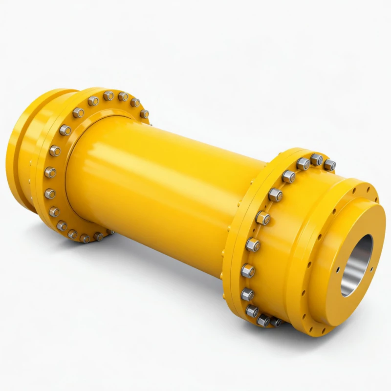
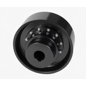
WGT Drum Shape Gear Coupling with Intermediate Sleeve
WGT drum shape gear coupling with intermediate sleeve for long-span shaft connections and axle withdrawal per JB/T7004. 24 sizes, 710 N·m to 1,250,000 N·m, up to 7500 RPM. Sleeve length H customisable from 75 mm. Type I and Type II. Y, J1, Z1 bores. Critical speed analysis included with every order.
WGT Drum Shape Gear Coupling with Intermediate Sleeve — High Rigidity, Axle Withdrawal
The WG-family solution for long-span shaft connections and axle withdrawal maintenance access. Removable intermediate sleeve spans the gap between two crowned-tooth coupling halves — disconnect the sleeve without moving either shaft. 24 sizes, widest torque range in the WG family. Factory direct to Australia.
Product Overview
The WGT drum shape gear coupling with intermediate sleeve is the member of the WG coupling family selected when two drive shafts are separated by a distance too large for a standard compact coupling, or when maintenance access to motor or driven machine shaft ends requires axle withdrawal capability — the ability to remove the intermediate sleeve from between the two coupling halves without disturbing either shaft or its alignment.
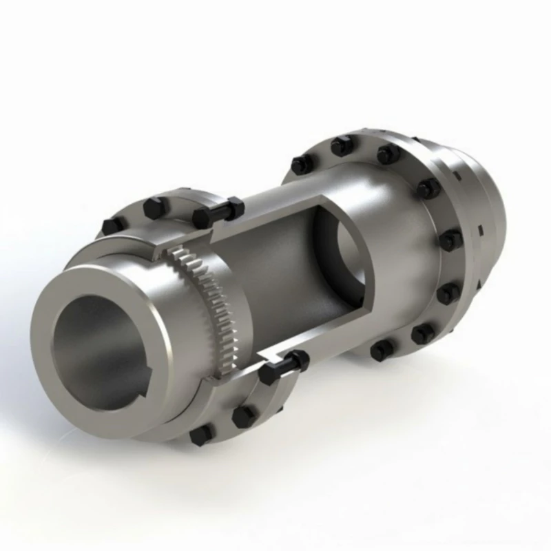
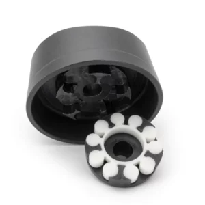
The WGT consists of three components: two crowned-tooth coupling halves (identical in design to the WG base series) mounted on their respective shafts, and an intermediate sleeve that spans the gap between them. The sleeve is a structural element — it transmits torque between the two halves through the crowned tooth mesh at each end, and can be removed and replaced without moving either shaft. This three-piece design provides what drive train engineers call a drop-out spacer — an invaluable maintenance feature on drives where access to bearing housings, shaft seals, or coupling hubs requires clear space between the motor and the driven machine.
The WGT covers the same 24-size range as the WG base series — from WGT1 (710 N·m) to WGT24 (1,250,000 N·m) — making it the most versatile intermediate shaft coupling in the WG family. GBC manufactures WGT couplings factory-direct and exports to Australian process industry, power generation, water utilities, and mining customers, with custom sleeve lengths and full material traceability documentation.
Technical Definition and Working Principle
The Three-Piece Architecture — Hubs, Sleeve, and the Axle Withdrawal Principle
The WGT's defining characteristic is its three-piece construction. Each coupling half consists of a hub with external crowned teeth that mesh with internal straight teeth in a short outer sleeve section. The intermediate sleeve — the central component that defines the WGT — connects the two outer sleeve sections and spans the shaft gap. Torque is transmitted from shaft to hub, through the crowned tooth mesh at each end of the sleeve, and across the sleeve body to the far coupling half.
Axle withdrawal works as follows: both hub hubs remain fixed to their respective shafts throughout the maintenance procedure. The outer sleeve sections at each end of the intermediate sleeve are disconnected, and the sleeve is slid axially clear of one or both coupling halves. This exposes the shaft ends, bearing housings, and hub faces without requiring any movement of the motor or driven machine. On a standard compact coupling, this same maintenance access would require coupling removal, shaft axial movement, and subsequent shaft realignment after maintenance — a procedure that typically takes 4–8 hours on a large industrial drive. With the WGT, axle withdrawal takes 20–40 minutes and requires no realignment after the sleeve is refitted.
The high rigidity of the WGT intermediate sleeve — compared to a flexible spacer design — is a key performance characteristic. The sleeve is a solid-walled steel tube machined to close tolerances, not a thin-walled or elastomeric component. This rigidity means the WGT transmits torque and accommodates misalignment through the gear tooth mesh alone, not through flexure of the spacer body — the same mechanism as all WG-family crowned-tooth gear couplings. The result is a spacer coupling with the full misalignment tolerance and torque capacity of the WG gear mesh, not the reduced capacity of flexible spacer designs.
Crowned Tooth Geometry and Misalignment on Long-Span Drives
Each end of the WGT intermediate sleeve carries a crowned-tooth gear mesh interface — two meshes in total, one per coupling half. Each mesh accommodates angular misalignment of 1.0 to 1.5 degrees, radial offset, and axial displacement independently. This means the WGT can accommodate misalignment at both shaft ends simultaneously, which is significant on long-span drives where the motor and driven machine may be misaligned relative to each other in both the horizontal and vertical planes.
The axial displacement capability is particularly important on WGT drives with long sleeves. Thermal expansion of the drive train during heat-soak — where the motor runs hot and the connected shaft expands axially — is absorbed by the axial sliding of both crowned tooth meshes within their respective outer sleeves. On a drive with a 500 mm WGT sleeve and operating temperature rise of 40 degrees Celsius, the thermal axial growth of the shaft between the two coupling halves can reach 0.3–0.5 mm, which is accommodated within the WGT's axial clearance without generating thrust forces at motor or gearbox bearings.
Critical Speed — The Engineering Constraint of Intermediate Sleeve Drives
The intermediate sleeve of the WGT acts as a rotating beam. Like any rotating beam, it has a critical speed — the rotational speed at which the sleeve's natural lateral vibration frequency coincides with the rotational frequency, causing resonant vibration. For short sleeves (at or near Hmin), the critical speed is well above the operating speed and requires no special attention. For longer sleeves, the critical speed decreases with the square of the sleeve length, and careful engineering analysis is required to ensure the operating speed does not approach the critical speed.
The WGT catalogue provides the weight and inertia per 10 mm of added sleeve length for each size, enabling engineers to perform critical speed calculations for specific H values. The allowable rotational speed decreases as H increases — the catalogue provides a table of allowable speed vs H length that must be consulted when specifying the sleeve length. Our engineering team performs this calculation as a standard part of the WGT order process when the sleeve length and operating speed are provided.
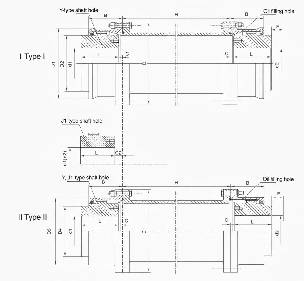
Type I and Type II Construction
For WGT1 through WGT14, both Type I (single outer sleeve) and Type II (with inner bore collar, B1 engagement) are available. Type II provides greater hub engagement length and is preferred on drives with significant axial thrust or shock loading. For WGT15 through WGT24, only Type I is available due to the dimensions of these larger sizes. Both types accept the same sleeve length H range starting from the specified Hmin for each size.
Comparison with Other Coupling Types for Long-Span Drives
| Feature | WGT (this product) | WG (compact) | Flexible Spacer Coupling | Jaw Coupling |
|---|---|---|---|---|
| Axle Withdrawal | Yes — sleeve removes without shaft movement | No — shaft must move axially | Yes — spacer drops out | No |
| Shaft Span Capability | Customisable H from Hmin upward | Fixed B dimension only | Variable length available | Fixed only |
| Torque Transmission Method | Crowned gear teeth — rigid | Crowned gear teeth — rigid | Disc pack or elastomer — flexible | Elastomer — flexible |
| Angular Misalignment Tolerance | 1.0–1.5 deg per mesh (2 meshes) | 1.0–1.5 deg per mesh (2 meshes) | Up to 1 deg (disc); higher (elastomer) | Up to 1 deg |
| Shock Load Tolerance | Excellent — crowned teeth | Excellent | Poor (disc) / Good (elastomer) | Good |
| Critical Speed Engineering | Required for longer H sleeves | Not applicable | Required for longer spacers | Not applicable |
WGT in the WG Family — When Shaft Span and Maintenance Access Drive the Selection
The WGT is one of five variants in the WG coupling family and is unique in having an intermediate sleeve. All five variants share the crowned gear mesh principle. The WGT is the correct choice when shaft spacing or maintenance access requirements cannot be met by any other member of the family.
| Factor | WG | WGP | WGC | WGZ | WGT |
|---|---|---|---|---|---|
| Standard | JB/T8854.2 | JB/T7001 | JB/T7002-93 | JB/T7003-93 | JB/T7004 |
| Intermediate Sleeve | No | No | No | No | Yes — customisable H |
| Axle Withdrawal | No | No | No | No | Yes |
| Braking Feature | None | Flat disc — caliper | None | Drum — shoe brake | None |
| Shaft Orientation | Horizontal | Horizontal | Vertical | Horizontal | Horizontal |
| Number of Sizes | 24 | 14 | 14 | 14 | 24 |
| Choose When... | Standard horizontal close-coupled drive | Caliper disc brake required | Vertical shaft drive | Shoe brake required | Long shaft span; axle withdrawal needed; distant motor-gearbox layout |
Specifications & Size Matrix — WGT1 to WGT24
All specifications are from the WGT catalogue per JB/T7004. Dimensions in millimetres. H is the minimum sleeve length; any H at or above Hmin can be supplied. Weight, inertia, and lubricant values are per coupling assembly at minimum H, excluding the sleeve. The "per 10 mm sleeve" table below shows the additional weight and inertia per each 10 mm of sleeve length added beyond Hmin. Critical speed must be verified when H significantly exceeds Hmin — contact our engineering team for critical speed analysis.
WGT1 – WGT14 Specifications (Type I and Type II)
| Size | Torque (N·m) |
Speed (rpm) |
Bore Range (mm) |
Y bore | J1 bore | D | D1 | D2 | D4 | B | Hmin (mm) |
Weight I (Kg) |
Weight II (Kg) |
Lube I (Kg) |
Lube II (Kg) |
|---|---|---|---|---|---|---|---|---|---|---|---|---|---|---|---|
| WGT1 | 710 | 7500 | 12–42 | 32–112 | –/44/84 | 122 | 115 | 98 | 60 | 58 | 75 | 5.66 | 4.86 | 0.085 | 0.04 |
| WGT2 | 1250 | 6700 | 22–56 | 52–112 | –/60/84 | 150 | 145 | 118 | 77 | 68 | 80 | 9.78 | 7.48 | 0.09 | 0.06 |
| WGT3 | 2500 | 6300 | 22–63 | 52–142 | –/60/107 | 170 | 165 | 140 | 90 | 80 | 80 | 16.7 | 12.2 | 0.17 | 0.10 |
| WGT4 | 4500 | 5600 | 30–80 | 82–172 | –/84/132 | 200 | 195 | 160 | 112 | 90 | 100 | 25.6 | 19.6 | 0.25 | 0.15 |
| WGT5 | 7100 | 5300 | 30–90 | 82–172 | –/84/132 | 225 | 215 | 180 | 128 | 100 | 100 | 35.0 | 26.1 | 0.35 | 0.22 |
| WGT6 | 10000 | 5000 | 32–100 | 82–212 | –/107/167 | 245 | 230 | 200 | 145 | 112 | 100 | 51.6 | 38.0 | 0.40 | 0.29 |
| WGT7 | 14000 | 4500 | 32–110 | 82–212 | –/107/167 | 272 | 265 | 230 | 160 | 122 | 120 | 68.6 | 45.0 | 0.60 | 0.44 |
| WGT8 | 20000 | 4250 | 55–125 | 112–212 | –/107/167 | 290 | 272 | 245 | 176 | 136 | 120 | 79.5 | 55.8 | 0.75 | 0.55 |
| WGT9 | 25000 | 4000 | 65–140 | 142–252 | 107/202 | 315 | 305 | 265 | 190 | 140 | 155 | 106.5 | 80.5 | 1.0 | 0.79 |
| WGT10 | 40000 | 3550 | 75–160 | 142–302 | 107/242 | 355 | 340 | 300 | 225 | 165 | 155 | 158.8 | 121.8 | 1.3 | 0.9 |
| WGT11 | 56000 | 3000 | 85–180 | 172–302 | 132/242 | 412 | 385 | 345 | 256 | 180 | 175 | 216.6 | 169.6 | 1.6 | 1.23 |
| WGT12 | 80000 | 2800 | 120–200 | 212–352 | 167/282 | 440 | 435 | 375 | 288 | 207 | 205 | 305.3 | 245.3 | 2.6 | 1.90 |
| WGT13 | 112000 | 2500 | 140–220 | 252–352 | 202/282 | 490 | 480 | 425 | 320 | 235 | 205 | 394.5 | 313.5 | 3.3 | 2.4 |
| WGT14 | 160000 | 2300 | 160–260 | 302–410 | 242/330 | 545 | 540 | 462 | 362 | 265 | 240 | 529.5 | 430.5 | 4.8 | 3.7 |
WGT15 – WGT24 Specifications (Type I Only)
| Size | Torque (N·m) | Speed (rpm) | Bore Range (mm) | Y bore length | D | D2 | D4 | B | Hmin (mm) | Weight I (Kg) | Lube I (Kg) |
|---|---|---|---|---|---|---|---|---|---|---|---|
| WGT15 | 224000 | 2100 | 160–280 | 302–470 | 580 | 488 | 400 | 280 | 240 | 684.5 | 5 |
| WGT16 | 280000 | 1900 | 180–300 | 302–470 | 650 | 560 | 440 | 300 | 240 | 948.2 | 7 |
| WGT17 | 355000 | 1800 | 200–320 | 352–470 | 690 | 600 | 460 | 325 | 280 | 1059 | 8 |
| WGT18 | 450000 | 1700 | 220–360 | 352–550 | 750 | 650 | 510 | 350 | 280 | 1399 | 10 |
| WGT19 | 560000 | 1600 | 240–380 | 410–550 | 775 | 690 | 535 | 372 | 350 | 1544 | 11 |
| WGT20 | 710000 | 1500 | 260–400 | 410–650 | 825 | 730 | 580 | 393 | 350 | 2099 | 13 |
| WGT21 | 800000 | 1300 | 280–440 | 470–650 | 925 | 825 | 620 | 404 | 350 | 2482 | 20 |
| WGT22 | 900000 | 950 | 320–460 | 470–650 | 950 | 850 | 665 | 415 | 400 | 2797 | 26 |
| WGT23 | 1000000 | 900 | 360–500 | 550–650 | 1030 | 900 | 710 | 440 | 400 | 3183 | 29 |
| WGT24 | 1250000 | 850 | 380–520 | 550–800 | 1060 | 925 | 730 | 450 | 400 | 3801 | 32 |
Intermediate Sleeve Incremental Weight and Inertia — Per 10 mm of Added Sleeve Length
Use these values to calculate total system weight and rotational inertia for any sleeve length H above Hmin. Total weight = coupling halves weight + (sleeve additional weight/10mm) x (H - Hmin)/10. Critical speed must be verified separately for the specified H value.
| Size | Max Speed (rpm) |
Hmin (mm) |
Add. Weight I per 10mm (Kg) |
Add. Weight II per 10mm (Kg) |
Add. Inertia I per 10mm (Kg·m²) |
Add. Inertia II per 10mm (Kg·m²) |
|---|---|---|---|---|---|---|
| WGT1 | 7500 | 75 | 0.088 | 0.08 | 0.00011 | 0.000088 |
| WGT2 | 6700 | 80 | 0.13 | 0.125 | 0.00022 | 0.00021 |
| WGT3 | 6300 | 80 | 0.16 | 0.16 | 0.00041 | 0.00038 |
| WGT4 | 5600 | 100 | 0.20 | 0.19 | 0.0008 | 0.00071 |
| WGT5 | 5300 | 100 | 0.23 | 0.22 | 0.0012 | 0.0010 |
| WGT6 | 5000 | 100 | 0.26 | 0.24 | 0.0017 | 0.0013 |
| WGT7 | 4500 | 120 | 0.32 | 0.30 | 0.0030 | 0.0027 |
| WGT8 | 4250 | 120 | 0.32 | 0.30 | 0.0030 | 0.0030 |
| WGT9 | 4000 | 155 | 0.42 | 0.40 | 0.0045 | 0.006 |
| WGT10 | 3500 | 155 | 0.46 | 0.45 | 0.0064 | 0.009 |
Note: For WGT11–WGT24 incremental sleeve data, and for allowable rotational speed vs H length tables, contact our engineering team or refer to the full catalogue. Critical speed must always be verified when specifying H significantly above Hmin, particularly for sizes WGT1–WGT10 at high operating speeds.
Custom Sleeve Length H, Non-Standard Bore, and Critical Speed Analysis Available
Specify any H value at or above Hmin. We machine each sleeve to the exact H required and perform critical speed verification for your operating speed and H combination as part of every WGT order. Send us your motor-to-driven-machine shaft gap, shaft bore data, and operating speed for a same-day engineering assessment.
Industries & Applications in Australia
The WGT is specified whenever a drive layout cannot use a standard compact coupling because the motor and driven machine shafts are too far apart, or when the maintenance program requires axle withdrawal capability to service motor or gearbox shaft-end components without a full decoupling and realignment procedure. Both conditions are common across Australian heavy industry.
Process Industry Pumps — Long Motor-to-Pump Shaft Spans
Equipment: Long-span pump drives where a structural frame separates the motor from the pump bearing housing, chemical process pump drives with maintenance access requirements, water treatment high-service pump drives with motor-pump air gaps for ventilation.
Process pump installations in Australian water treatment, chemical processing, and mineral processing plants frequently specify motor-to-pump air gaps of 100–500 mm to provide ventilation, electrical clearance, or maintenance access around the shaft coupling zone. The WGT bridges this gap with a high-rigidity intermediate sleeve, eliminating the need for a separate support bearing in the shaft span — which a long unsupported shaft would otherwise require. The axle withdrawal capability means pump mechanical seal or bearing replacement can proceed with sleeve removal in under 30 minutes, versus the 4–6 hours required for full coupling disassembly and shaft realignment. Explore the full coupling product range at australia-drive.com.
Power Generation — Turbine and Generator Drive Trains
Equipment: Gas turbine generator couplings, steam turbine auxiliary drive couplings, diesel generator sets with long shaft spans, hydro turbine auxiliary drives.
Power station drive trains in Australian thermal, hydro, and gas power generation facilities use WGT-type intermediate sleeve couplings on auxiliary equipment where the structural layout places the motor and driven machine shafts too far apart for compact coupling, but where the maintenance access requirement for turbine-end bearing or mechanical seal work requires axle withdrawal to avoid full machine decoupling. WGT15 through WGT24 cover the high-torque range of large auxiliary drive applications in power stations.
Mining Conveyor and Mill Drive Trains — Motor Withdrawal Access
Equipment: Long-span conveyor head drive trains, ball mill and SAG mill motor-gearbox coupling, crusher main drive couplings where motor withdrawal access is a maintenance requirement.
Australian mine sites in the Pilbara, Hunter Valley, and Queensland use WGT couplings on conveyor and mill drive trains where the maintenance philosophy requires motor withdrawal access — the ability to slide the drive motor backward off the drive shaft for replacement without disturbing the gearbox or mill. The WGT's axle withdrawal capability provides exactly this access: the sleeve is removed, the motor slides back on its rails, and the gearbox input shaft remains in position. WGT10 through WGT24 cover the torque range of mine conveyor and mill drive applications.
Industrial Test Benches and Gearbox Development Rigs
Equipment: Industrial gearbox test benches, motor test rigs, transmission development test stands, fatigue test machines requiring variable shaft span.
Australian industrial test facilities at OEM workshops and research institutions use WGT couplings for test bench coupling sets where the shaft span between the drive motor and test item may vary between test programs. The WGT's customisable H sleeve allows the same coupling halves to be used with different sleeve lengths as the test configuration changes, and the axle withdrawal capability allows rapid test item changeover without full coupling disassembly. Contact our team to discuss your test bench coupling requirements.
Paper, Cement, and Steel Mill Line Shafts
Equipment: Paper machine section drives requiring roll bearing access, cement kiln auxiliary drives with structural constraints on motor placement, steel mill roll table drives with long drive shaft spans.
Process industries with continuous production machines — paper mills, cement plants, and steel rolling mills — specify WGT couplings on section drives where the mechanical layout requires a shaft gap between the drive motor and the driven roll or mechanism. On paper machine drives in Victoria and NSW, WGT couplings allow felt and wire roll bearing replacement during scheduled paper machine maintenance outages without requiring full motor decoupling — a time saving that directly reduces planned maintenance outage duration.
Technical Advantages — Crowned Tooth on Long-Span Drives
Higher Misalignment Tolerance — Both Shaft Ends, Independent Compensation
The WGT has two independent crowned-tooth meshes — one at each end of the intermediate sleeve. Each mesh independently accommodates 1.0–1.5 degrees of angular misalignment, meaning the WGT can tolerate misalignment at both shaft ends simultaneously. On long-span drives in Australian mining and process industry, where the motor foundation and gearbox/machine foundation may settle independently over time, this dual independent compensation is a significant practical advantage. A straight-tooth intermediate shaft coupling — which has no misalignment capability at either mesh — transmits all misalignment as bending stress into the intermediate shaft itself, risking fatigue failure of the shaft at the gear mesh interface under the accumulated misalignment of Australian foundation settlement conditions.
Longer Service Life Under Shock Loads
Long-span drives in Australian mining and process industry experience the same shock loading events as compact drives — crusher blockage clearance torque spikes, conveyor startup overloads, and mill charge impacting events. The WGT's crowned teeth distribute these peak loads as Hertzian contact ellipses at both mesh interfaces, with no edge stress concentration regardless of the misalignment state at either shaft end. In documented Australian conveyor and mill drive applications, WGT-type crowned intermediate shaft couplings consistently outlast straight-tooth equivalents by 3–5x under the same combined shock and misalignment duty.
Reduced Bearing Loads at Both Shaft Ends
On a long-span drive, misalignment-induced bending moments at the coupling interfaces load both the motor bearing and the gearbox or machine bearing. A straight-tooth intermediate shaft coupling transmits these bending moments at full intensity to both bearings. The WGT's self-centring crowned teeth minimise transmitted bending moments at both mesh interfaces, protecting both motor drive-end bearings and gearbox input bearings from misalignment-induced cyclic loading. This dual bearing protection is particularly valuable on long-span drives where the combined bearing replacement cost on a motor-gearbox pair may exceed the WGT coupling cost by 5–10x.
Lower Maintenance Frequency — Axle Withdrawal Plus Two Lubrication Ports
The WGT's axle withdrawal capability reduces the maintenance event duration for any work requiring shaft-end access from hours to minutes. Combined with two built-in lubrication ports (one per coupling half) that allow re-lubrication without disassembly at 6–12 month intervals, the WGT minimises both planned and unplanned maintenance on long-span drives. For Australian mine and process plant maintenance planners, the ability to perform bearing, seal, or hub work via axle withdrawal — without a full shaft realignment procedure after maintenance — directly reduces the critical path duration of planned outages.
Suitable for High-Speed Applications — Up to 7500 RPM (WGT1)
WGT1 is rated to 7500 RPM at minimum sleeve length, enabling direct 2-pole motor connections on 50 Hz supplies. For sizes WGT1 through WGT6 at speeds above 3000 RPM, sleeve length H must be verified against the critical speed table before specifying. The WGT's high-rigidity solid-tube sleeve — compared to the thin-walled hollow tubes used in some competing intermediate shaft couplings — provides a higher critical speed for a given diameter and length, permitting longer sleeves at higher operating speeds without critical speed concerns.
Manufacturing & Quality Assurance
Manufacturing Process
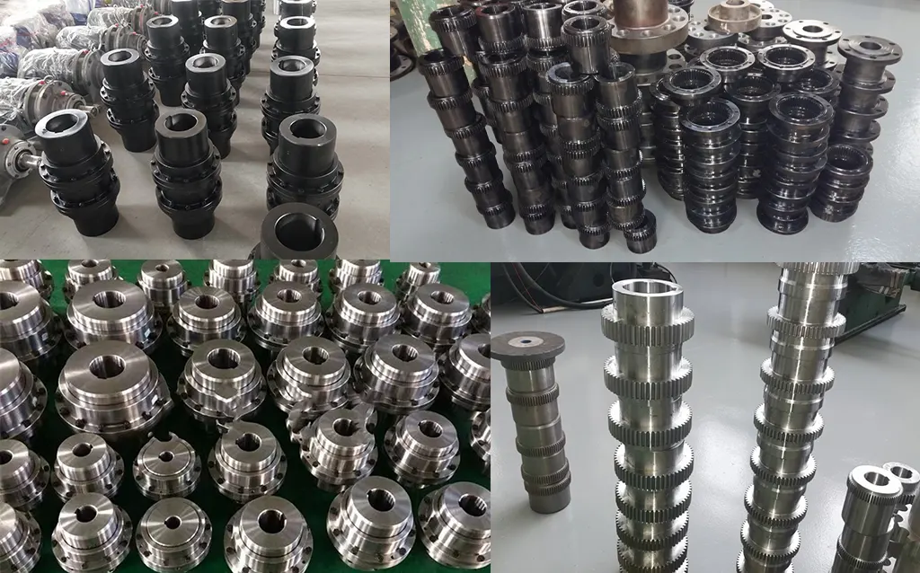
WGT coupling halves are manufactured from the same forged alloy steel blanks as the WG base series — 42CrMo4 for WGT8 and above, 45# carbon steel for smaller sizes. The intermediate sleeve is machined from seamless alloy steel tube, finish-turned to close concentricity tolerances on both inner and outer surfaces. The sleeve end faces are machined to perpendicularity within 0.02 mm to ensure correct engagement with the coupling half outer sleeves during assembly. Sleeve outer diameter is controlled to h6 tolerance to ensure a consistent fit with the coupling half sleeve bore.
The coupling crowned teeth are CNC hobbed to DIN Class 7 accuracy. Tooth flanks are carburised and quenched to HRC 58–62 surface hardness with HRC 30–35 core hardness. All bores are finished to H7 tolerance. Z1 taper bores are verified with taper gauges and blue-contact checks for minimum 70% contact. The assembled WGT (two halves plus sleeve) is dimensionally verified as a system before dispatch — sleeve-to-hub engagement, overall H dimension, and concentricity are all measured and recorded.
Quality Control Flow
Certifications
ISO 9001:2015 quality management certification covers the full WGT manufacturing process. CE marking applies to applicable sizes. Products manufactured per JB/T7004. Every shipment includes material mill certificates with heat traceability for all three components (both hubs and the sleeve), heat treatment records, Rockwell hardness test certificates, sleeve concentricity measurement records, and dimensional inspection reports for the assembled system including the H dimension verification.
Why Source Your WGT Couplings from GBC?
Engineering Support for Sleeve Length and Critical Speed
Specifying a WGT requires more engineering input than a standard compact coupling — the sleeve length H, critical speed verification, and incremental inertia calculations are all application-specific. GBC's engineering team performs these calculations as a standard part of every WGT order, providing a confirmed H dimension, critical speed margin, and total system inertia data for the specified operating speed and sleeve length combination. No other supplier in the WG-family product range provides this level of application engineering support as standard.
15+ Years Exporting to Australia
GBC has supplied WGT couplings to Australian process industry, mining, and power generation customers since 2010. We understand the documentation requirements of Australian industrial buyers — material traceability, heat treatment records, and dimensional inspection reports — and include these as standard in every WGT shipment. ISPM-15 packing is standard for all export orders.
English-Speaking Engineering Team
WGT orders require a technical dialogue — we need your motor-to-machine shaft gap, operating speed, shaft bore diameters, and whether axle withdrawal direction has been determined. Our engineers conduct this dialogue in clear technical English, confirm the sleeve length and critical speed, and provide an engineering data sheet for each WGT order that documents the key design parameters for your plant records.
Sleeve Replacement as a Standalone Spare
The intermediate sleeve is a replaceable component. If a sleeve is damaged — from a mechanical impact, corrosion, or fatigue from operation at or near critical speed — a replacement sleeve can be ordered as a standalone component to the original H dimension, without replacing the shaft-mounted hubs. This reduces the cost and lead time of WGT maintenance compared to full coupling replacement and eliminates the need for shaft realignment after sleeve replacement. Order a replacement sleeve here.
Full WG Family — One Supplier
As the manufacturer of WG, WGP, WGC, WGZ, and WGT, GBC supplies the complete family from a single source. Process plant projects requiring WGT on long-span drives and WG on compact drives are handled through one engineering team, one procurement order, and one documentation package.
Single Units and Project Quantities
WGT couplings and replacement sleeves are available from a single unit. Custom H dimensions add 5–10 working days to standard lead time. Standard sizes at Hmin ship within 15–20 working days ex-works. For project quantities of 10 or more identical units, contact our team for volume pricing and scheduling options.
Application Case Studies
Case 1: Water Treatment High-Service Pump Drive — Victoria
Customer Profile: A Victorian water authority operating 12 high-service pump stations, each with 200–315 kW motors coupled to centrifugal pumps through a 200 mm motor-to-pump shaft gap required for motor ventilation and maintenance access per the authority's pump station design standard.
Challenge: The authority's previous coupling specification used a hollow flexible spacer design that had experienced three fatigue failures of the spacer tube in 24 months across the 12 stations. Root cause analysis identified that the spacer tubes were experiencing resonant vibration because their critical speed had not been verified against the 1480 RPM operating speed and 220 mm sleeve length combination. The authority's rotating plant engineer needed a replacement solution with verified critical speed margin, axle withdrawal capability, and documented engineering analysis.
Solution: We supplied 12x WGT7 couplings (14,000 N·m, 90 mm bore, H = 200 mm, Type I) with full critical speed analysis confirming a critical speed of 4,250 RPM at H = 200 mm — a margin of 2.87x above the 1480 RPM operating speed. The higher tube wall thickness of the WGT sleeve versus the previous hollow flexible spacer was the primary factor in the improved critical speed margin.
Result: 30 months of operation across all 12 stations with zero coupling failures or vibration incidents. The authority's rotating plant engineer documented the critical speed calculation methodology as a new standard for all future spacer coupling specifications across the authority's pump station portfolio. The axle withdrawal capability has been used on four occasions to perform pump mechanical seal replacements, reducing seal replacement outage duration from an average of 5.5 hours (previous coupling) to 1.8 hours (WGT axle withdrawal).
Case 2: Iron Ore Conveyor Motor Withdrawal Drive — Pilbara, WA
Customer Profile: An iron ore producer in the Pilbara operating a 47 km overland conveyor with 12 drive stations, each requiring a 350 mm motor withdrawal gap for motor replacement by rail-mounted motor carriage — a maintenance design feature that allows rapid motor changeout without a crane on remote drive stations.
Challenge: The original compact WG couplings could not span the 350 mm withdrawal gap required for the motor carriage maintenance system. The site's maintenance manager had previously required temporary shaft blocking to perform motor changeouts, which added 2–3 hours to each motor replacement event. The engineering team required a coupling that could span the 350 mm gap reliably, tolerate the foundation settlement misalignment of the remote drive station pads, and allow motor withdrawal without sleeve disassembly from the motor shaft hub.
Solution: We supplied 12x WGT10 couplings (40,000 N·m, 140 mm bore, H = 350 mm, Type I) with critical speed verified at 2,820 RPM for the specified H — a 1.98x margin above the 1480 RPM motor speed. The sleeve is designed to be detached from the gearbox-side hub and slid back with the motor during withdrawal, then refitted during motor installation without realignment of the gearbox hub.
Result: Motor changeout time reduced from an average of 7.2 hours (previous method with shaft blocking) to 3.1 hours (WGT axle withdrawal). The savings across the 12-drive fleet at an average of 2 motor changeouts per year per drive: approximately 98 hours of drive station downtime recovered annually. At the mine's estimated conveyor downtime cost of AUD $3,800 per hour, the annual saving exceeds AUD $372,000.
Case 3: Paper Machine Section Drive — Victoria
Customer Profile: A tissue paper mill in regional Victoria operating a tissue machine with 18 section drives, each rated 15–90 kW, where the drive motor and section roll bearing housing are separated by 150–250 mm depending on the section, with roll bearing replacement frequency averaging 4–6 times per year per section.
Challenge: The paper machine's 18 section drives used flexible disc-pack spacer couplings that had adequate torque capacity but poor shock load tolerance — the occasional web break on the paper machine created torsional shock pulses that fatigued the disc packs within 6–8 months. Roll bearing replacement with the disc-pack couplings required 3.5 hours per section due to disc-pack removal and reinstallation procedures, which was unacceptably long given the bearing replacement frequency.
Solution: We supplied 18x WGT couplings in sizes WGT3 to WGT6 (2,500–10,000 N·m, sleeves from H = 155 to H = 250 mm depending on section) replacing the disc-pack spacers. The WGT's crowned tooth shock tolerance addressed the web-break fatigue failure mode, and the axle withdrawal capability dramatically simplified bearing replacement.
Result: Zero coupling failures from web-break torsional shocks across all 18 sections in 28 months since installation. Roll bearing replacement time reduced from 3.5 hours to 55 minutes per section via axle withdrawal, saving approximately 210 hours of machine section downtime per year across the 18-section drive fleet. The mill's maintenance planner reported this as the single largest maintenance time reduction across the entire tissue machine drive train.
Frequently Asked Questions
What is a WGT drum shape gear coupling with intermediate sleeve?
The WGT (JB/T7004) is a crowned-tooth gear coupling with a customisable-length intermediate sleeve (middle set) that connects two coupling halves across a shaft gap. It is used for long-span shaft connections and where axle withdrawal — removing the sleeve without disturbing either shaft — is required for maintenance access. 24 sizes cover WGT1 (710 N·m) to WGT24 (1,250,000 N·m), up to 7500 RPM. Type I and Type II are available for WGT1–WGT14.
What is the minimum sleeve length H for a WGT coupling?
Minimum H values range from 75 mm (WGT1) to 400 mm (WGT15–WGT24). The minimum is determined by the required axle withdrawal clearance and structural stiffness of the sleeve. Any H value at or above Hmin for the chosen WGT size can be supplied. For H values significantly above Hmin, critical speed must be verified — our engineering team performs this calculation for every WGT order as a standard service.
How does axle withdrawal work on a WGT coupling?
Both coupling hubs remain mounted on their respective shafts. To withdraw the sleeve, the fasteners connecting the sleeve to one or both outer hub sleeves are released, and the intermediate sleeve is slid axially clear of one coupling half. This exposes the shaft end, bearing housing, and hub face without requiring any shaft movement. After maintenance, the sleeve is refitted and fasteners are retorqued — no shaft realignment is required because neither shaft has moved.
What is the critical speed consideration for WGT sleeves?
The intermediate sleeve acts as a rotating beam whose natural lateral vibration frequency (critical speed) decreases with increasing H length. If the operating speed approaches the critical speed, resonant vibration occurs, risking sleeve fatigue failure. For standard short H values near Hmin, the critical speed is well above operating speed. For longer H values, engineering verification is required. We perform this calculation for every WGT order. The catalogue provides weight and inertia per 10 mm of added sleeve length to support customer calculations.
How many lubrication points does a WGT coupling have?
Two — one per coupling half. Each half is re-lubricated independently through its own built-in lubrication port with EP grease or gear oil. The total lubricant volume in the specification table is the combined fill for both halves. The intermediate sleeve carries no lubrication requirement. Standard re-lubrication intervals are 6–12 months per half, and both halves should be re-lubricated at the same service interval.
Can the intermediate sleeve be replaced independently?
Yes. The sleeve is a separate component that can be ordered and replaced independently of the two coupling hubs. When ordering a replacement sleeve, specify the WGT size and required H dimension. Replacement sleeves are machined to the same specifications as new assemblies and include dimensional inspection records. Since the hubs remain on their shafts during sleeve replacement, no realignment is required after fitting the new sleeve.
Specify Your WGT Coupling and Sleeve Length
Send us your motor-to-machine shaft gap (required H), transmission torque, operating speed, shaft bore diameters, and construction type preference (I or II). Our engineering team confirms the right WGT size, verifies critical speed, and provides a factory-direct quotation with full engineering data sheet within 24 hours.
|
Critical speed analysis included
|
sales@australia-drive.com
GBC — Factory-direct WGT drum shape gear couplings with intermediate sleeve for Australian process industry, mining, power generation, and maintenance-critical drive applications since 2010.
WGT drum shape gear coupling with intermediate sleeve for long-span shaft connections and axle withdrawal per JB/T7004. 24 sizes, 710 N·m to 1,250,000 N·m, up to 7500 RPM. Sleeve length H customisable from 75 mm. Type I and Type II. Y, J1, Z1 bores. Critical speed analysis included with every order.
Related products
-
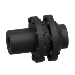
LMS / MLS Type Double-Flange Plum Blossom Jaw Coupling
-
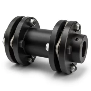
SJM Type Double Flexible Diaphragm Coupling
-
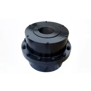
CL Type Gear Coupling
-
NGCLZ Drum Shape Gear Coupling with Brake Drum | Intermediate Shaft Type
-
LMZ-I Type Plum Blossom Coupling with Split Brake Wheel
-
SWP-C Short Non-Flexible Universal Joint Couplings