JS Shell Horizontal Mount Grid Coupling
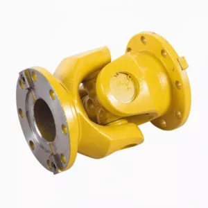
The JS Shell Horizontal Mount Grid Coupling features a horizontally split clamping shell for axial-direction access to serpentine spring elements. Rated from 45 to 800,000 N·m across 25 sizes, this coupling excels in installations requiring lateral maintenance clearance and delivers exceptional torsional damping for process-critical drives.
JS Shell Horizontal Mount Grid Coupling – Axial-Access Serpentine Spring Coupling
The JS Shell Horizontal Mount Grid Coupling is a metallic flexible coupling variant within the JS grid coupling family, distinguished by its horizontally oriented clamping shell that provides axial-direction access to the internal serpentine spring element. This configuration is purpose-engineered for installations where radial clearance around the coupling is restricted – such as enclosed machine bases, tight pump skids, or multi-shaft gearbox arrangements – but adequate axial space exists for shell removal along the shaft centerline.
Sharing the same proven serpentine spring technology as the radial mount variant, the horizontal mount version offers identical torque ratings from 45 N·m (JS1) to 800,000 N·m (JS25), the same 99.47% transmission efficiency, and the same 36% average vibration damping ratio. The differentiator lies purely in the shell geometry and maintenance access direction, giving plant engineers the flexibility to choose the optimal configuration for each specific installation footprint.
Engineering Advantages of the Horizontal Mount Design
Axial Shell Removal
The clamping shell slides off along the shaft axis rather than lifting radially, enabling spring service in confined radial spaces typical of packaged pump sets and compact machine frames.
Same Torque Performance
Identical torque capacity, speed limits, and shaft bore ranges as the radial mount series – 25 sizes from 45 to 800,000 N·m – ensuring interchangeable selection for new designs or retrofits.
Size-Adapted Shell Material
Models JS1 through JS22 feature aluminum alloy shells for reduced rotating mass, while JS23 through JS25 employ fabricated steel shells to handle the structural demands of ultra-high-torque applications.
36% Vibration Damping
The serpentine spring absorbs torsional oscillations through progressive elastic deflection, protecting downstream gearboxes, bearings, and process equipment from resonance-induced fatigue.
Dual Overload Safety
Rated to sustain peak torque loads at twice the nominal value for short durations, safeguarding the drivetrain during motor start-up, load reversals, and process upsets.
Integrated Lubrication
Each size includes a dedicated lubrication port for periodic re-greasing without shell removal, extending maintenance intervals to 2,000–4,000 operating hours in standard environments.
Structural Configuration and Shell Variants
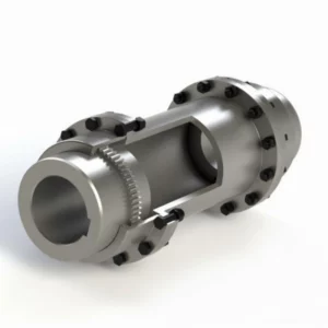
The horizontal mount grid coupling retains the same five-component architecture as the radial mount variant, with the critical distinction being the shell orientation and clamping method:
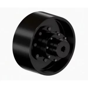
1 & 5 – Half Couplings: Identical hub halves with precision-cut tooth profiles that engage the serpentine spring. Standard keyway bores available across the full diameter range.
2 – Horizontal Clamping Shell: Unlike the radial shell that lifts vertically, this shell is oriented to slide axially. Four distinct shell configurations are used across the size range to optimize structural integrity and weight.
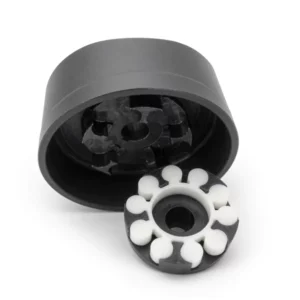
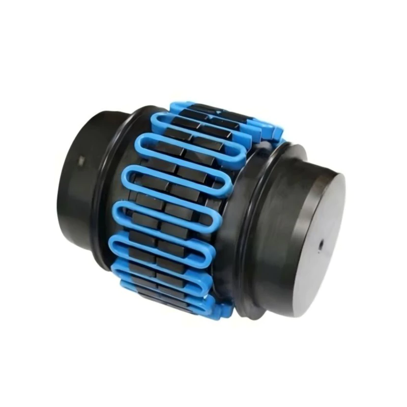
3 – Serpentine Spring: Premium spring steel element – the same specification used in the radial mount version – ensuring consistent torque transmission and damping behavior.
4 – Lubrication Port: Positioned for accessibility in horizontal orientation, permitting scheduled re-greasing during operation or brief maintenance stops.
Shell configuration by model range: JS1–JS13 use a compact single-piece horizontal shell. JS14–JS19 use a two-piece bolted shell to accommodate larger diameters. JS20–JS22 feature a heavy-duty flanged shell design. JS23–JS25 use steel fabricated shells for maximum rigidity.
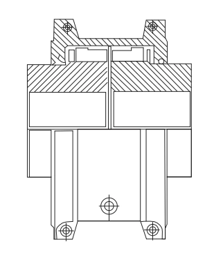
Fig. 1 – JS horizontal mount grid coupling: cross-section with axial-access shell and four shell variant outlines by size range
The horizontal mount design is particularly favored in process industry coupling applications where equipment is installed on shared baseplates with minimal radial clearance between adjacent machines.
Technical Specifications – JS Horizontal Mount Grid Coupling (Complete Range)
The complete specification table covers all 25 sizes of the JS horizontal mount variant. Compared to the radial mount version, this table includes the overall shell length (L₀) dimension relevant to axial clearance planning. All dimensions in millimeters.
| Model | Nominal Torque Tn (N·m) |
Max Speed (rpm) |
Shaft Bore d (mm) | Bore Length L (mm) |
Overall Length L₀ (mm) |
L₂ (mm) | D (mm) | D₁ (mm) | Clearance t (mm) |
Clearance C (mm) |
Weight (kg) |
Moment of Inertia I (kg·m²) |
Lubricant (kg) |
|---|---|---|---|---|---|---|---|---|---|---|---|---|---|
| JS1 | 45 | 4500 | 18, 19; 20, 22, 24; 25, 28 | 47 | 97 | 66 | 95 | – | – | 3 | 1.91 | 0.00141 | 0.0272 |
| JS2 | 140 | 4500 | 22, 24; 25, 28; 30, 32, 35 | 47 | 97 | 68 | 105 | – | – | 3 | 2.59 | 0.00223 | 0.0408 |
| JS3 | 224 | 4500 | 25, 28; 30, 32, 35, 38; 40, 42 | 50 | 103 | 70 | 115 | – | – | 3 | 3.36 | 0.00327 | 0.0544 |
| JS4 | 400 | 4500 | 32, 35, 38; 40, 42, 45, 48, 50 | 60 | 123 | 81 | 130 | – | – | 3 | 5.44 | 0.00727 | 0.068 |
| JS5 | 630 | 4350 | 40, 42, 45, 48, 50, 55, 56 | 63 | 129 | 94 | 150 | – | – | 3 | 7.26 | 0.0119 | 0.0862 |
| JS6 | 900 | 4125 | 48, 50, 55, 56; 60, 63, 65 | 76 | 155 | 97 | 160 | – | – | 3 | 10.4 | 0.0185 | 0.113 |
| JS7 | 1,800 | 3600 | 55, 56; 60, 63, 65, 70, 71, 75; 80 | 89 | 181 | 115 | 190 | – | – | 3 | 17.7 | 0.0451 | 0.172 |
| JS8 | 3,150 | 3600 | 65, 70, 71, 75; 80, 85, 90, 95 | 98 | 199 | 122 | 210 | – | 3 | – | 25.4 | 0.0787 | 0.254 |
| JS9 | 5,600 | 2440 | 75; 80, 85, 90, 95; 100, 110 | 120 | 245 | 155 | 250 | – | 5 | – | 42.2 | 0.178 | 0.426 |
| JS10 | 8,000 | 2250 | 85, 90, 95; 100, 110, 120 | 127 | 259 | 162 | 270 | – | – | 5 | 54.4 | 0.27 | 0.508 |
| JS11 | 12,500 | 2025 | 90, 95; 100, 110, 120, 125; 130, 140 | 149 | 304 | 191 | 310 | – | – | 6 | 81.2 | 0.514 | 0.735 |
| JS12 | 18,000 | 1800 | 110, 120, 125; 130, 140(, 150); 160, 170 | 162 | 330 | 195 | 346 | – | – | 6 | 121 | 0.989 | 0.907 |
| JS13 | 25,000 | 1600 | 120, 125; 130, 140, 150; 160, 170, 180; 190, 200 | 184 | 374 | 201 | 384 | – | – | – | 178 | 1.85 | 1.13 |
| JS14 | 35,500 | 1500 | 140, 150; 160, 170, 180; 190, 200 | 183 | 372 | 271 | 450 | 391 | – | – | 227 | 3.49 | 1.95 |
| JS15 | 50,000 | 1300 | 160, 170, 180; 190, 200, 220; 240 | 198 | 402 | 278 | 500 | 431 | – | 6 | 309 | 5.82 | 2.81 |
| JS16 | 63,000 | 1200 | 180; 190, 200, 220; 240, 250, 260; 280 | 216 | 438 | 307 | 566 | 487 | – | 6 | 448 | 10.4 | 3.49 |
| JS17 | 90,000 | 1100 | 200, 220; 240, 250, 260; 280, 300 | 239 | 484 | 321 | 630 | 555 | – | – | 619 | 18.3 | 3.76 |
| JS18 | 125,000 | 1000 | 240, 250, 260; 280, 300, 320 | 260 | 526 | 325 | 675 | 608 | – | – | 776 | 26.1 | 4.4 |
| JS19 | 160,000 | 900 | 280, 300, 320; 340, 360 | 280 | 566 | 355 | 756 | 660 | – | – | 1,057 | 43.5 | 5.62 |
| JS20 | 224,000 | 820 | 300, 320; 340, 360, 380 | 305 | 623 | 423 | 845 | 751 | – | – | 1,424 | 75.5 | 10.53 |
| JS21 | 315,000 | 730 | 320; 340, 360, 380; 400, 420 | 325 | 663 | 490 | 920 | 822 | – | 13 | 1,785 | 113 | 16.1 |
| JS22 | 400,000 | 680 | 340, 360, 380; 400, 420, 440, 450 | 345 | 703 | 546 | 1000 | 905 | – | 13 | 2,267 | 175 | 24.06 |
| JS23 | 500,000 | 630 | 360, 380; 400, 420, 440, 450, 460, 480 | 368 | 749 | 648 | 1087 | – | – | – | 2,950 | 339 | 33.82 |
| JS24 | 630,000 | 580 | 400, 420, 440, 450, 460 | 401 | 815 | 698 | 1180 | – | – | – | 3,833 | 524 | 50.17 |
| JS25 | 800,000 | 540 | 420, 440, 450, 460, 480, 500 | 432 | 877 | 762 | 1260 | – | – | – | 4,682 | 711 | 67.24 |
Note: Weight calculated without bore holes. Shaft bores can be manufactured to customer requirements. Shell material: JS1–JS22 aluminum alloy, JS23–JS25 steel. Semicolons in bore listings separate available diameter groupings.
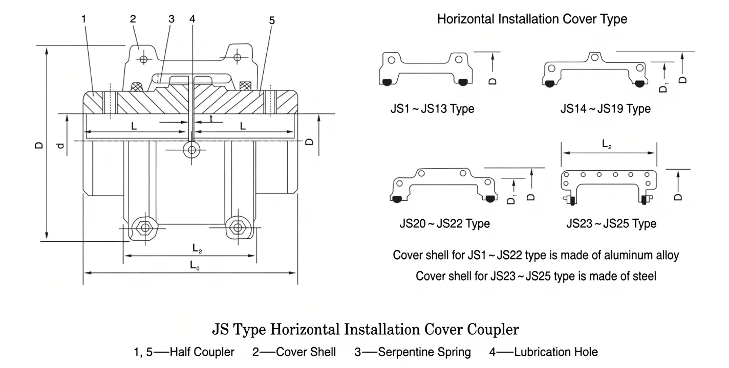
Fig. 2 – JS horizontal clamping shell configuration detail
Optimal Application Scenarios
While sharing identical torque and vibration performance with the radial mount variant, the horizontal mount grid coupling is the preferred choice in specific installation scenarios:
Petrochemical Pump Drives
API pump skids often feature tight radial envelopes between pump and motor. The axial-access shell allows spring service from the drive end without removing guards or adjacent piping.
Water & Wastewater Treatment
Horizontal-shaft aerators, clarifier drives, and raw water pump stations benefit from the coupling’s vibration damping, reducing noise transmission through concrete baseplates in inhabited areas.
Marine & Offshore
Engine room installations with restricted overhead clearance for crane access. The horizontal shell slides along the shaft without needing vertical lifting height above the coupling.
Paper & Pulp Processing
Press section drives and calendar roll couplings in paper mills where precise torque control and rapid maintenance turnaround directly impact production uptime and sheet quality.
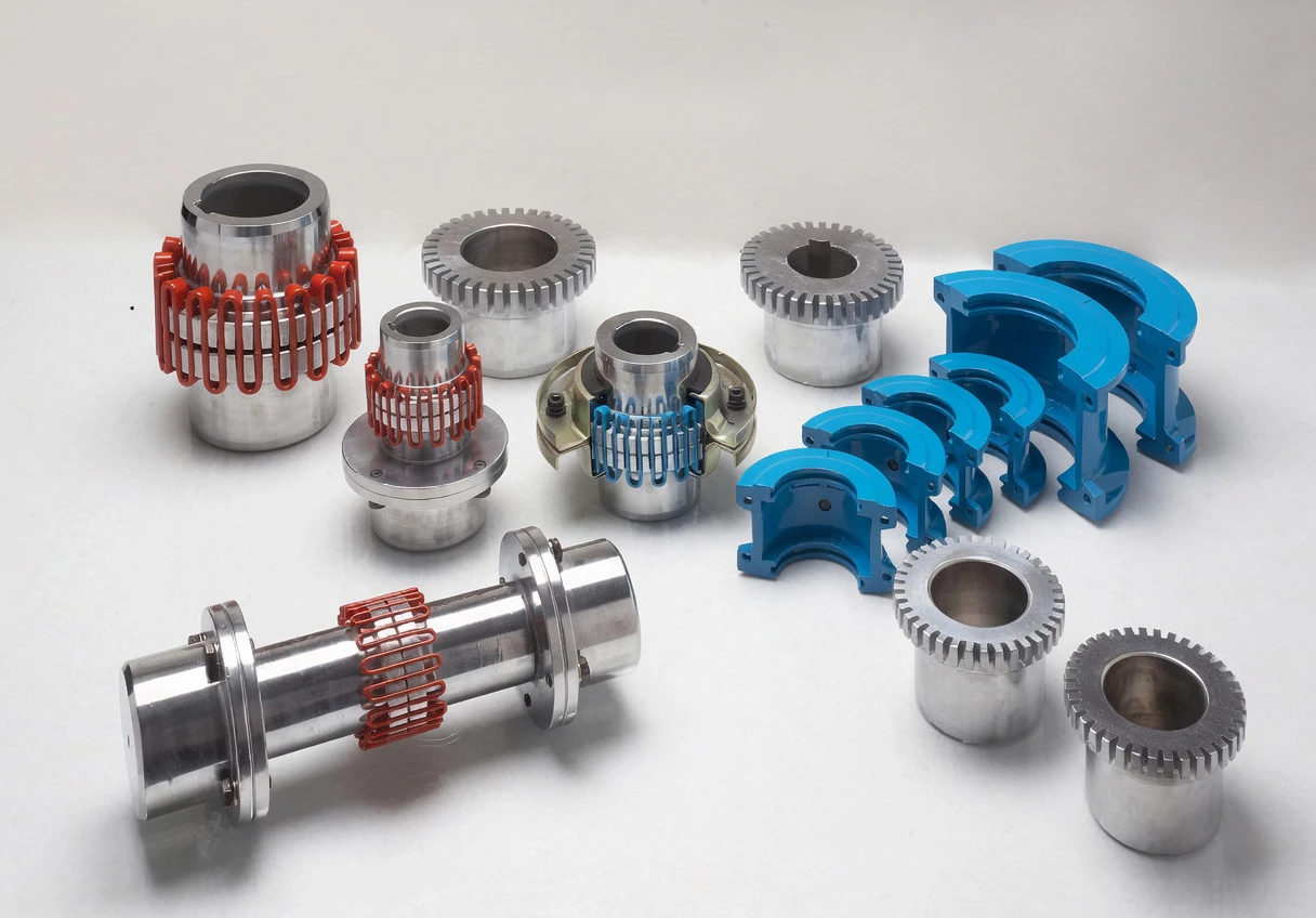
GBC grid coupling product range – engineered for reliability across all industrial sectors
Radial Mount vs. Horizontal Mount – Selection Considerations
| Criterion | JS Radial Mount | JS Horizontal Mount |
|---|---|---|
| Shell removal direction | Radial (perpendicular to shaft) | Axial (along shaft centerline) |
| Best when space is limited | Axially | Radially |
| Torque range | 45 – 800,000 N·m | 45 – 800,000 N·m |
| Number of sizes | 25 (JS1–JS25) | 25 (JS1–JS25) |
| Transmission efficiency | 99.47% | 99.47% |
| Overall length (L₀) | Shorter (no axial shell extension) | Longer (shell extends axially) |
| Typical installation | Open machine halls, cranes, mills | Enclosed skids, pump sets, marine |
Both variants accept the same serpentine spring replacement elements, so sites operating both mount types can consolidate spare spring inventory.
Coupling Selection Methodology
The selection process for the horizontal mount variant follows the same engineering methodology as the radial mount, with an additional dimensional check for the overall shell length (L₀).
Design Torque Calculation
Determine the calculated torque: Tc = K × 9550 × Pw / n
Where Pw is drive power (kW), n is operating speed (rpm), and K is the service factor derived from prime mover type and driven machine classification. Ensure Tc ≤ Tn for the chosen coupling size.
Dimensional Verification
In addition to bore diameter and torque matching, verify that the L₀ dimension (overall shell length) fits within the available axial space between the driving and driven machine frames. Allow an additional 10–15 mm axial clearance beyond L₀ for shell insertion and removal access during maintenance.
Misalignment Tolerances
The JS horizontal mount grid coupling accommodates the same misalignment values as the radial mount version: radial offset (ΔY) from 0.15 to 0.5 mm, angular misalignment up to 0.5°, and axial displacement (ΔX) within ±0.3 to ±0.6 mm depending on coupling size. Tighter installation alignment always extends coupling and bearing service life.
Customer Reviews & Field Performance
★★★★★ – Refinery, Saudi Arabia
Industry: Petrochemical | Application: Centrifugal Pump Drive
“We replaced gear couplings with JS9 horizontal mount grid couplings on six API 610 process pumps handling naphtha feed. The axial shell access was critical since our pump skids have only 80 mm radial clearance to the baseplate edge. After 14 months, bearing temperatures on the pump side reduced by 12°C, and we have had zero unplanned coupling outages.”
– Rotating Equipment Engineer, Jubail Refinery Complex
★★★★★ – Pulp Mill, Canada
Industry: Paper & Pulp | Application: Press Section Drive
“Our press section operates at 1,200 rpm with frequent torque spikes during felt changes. The JS7 horizontal mount coupling absorbed these transients without any measurable spring wear over 24 months. The key benefit was maintenance speed – our millwrights replaced the spring in 45 minutes during a scheduled felt change without needing to realign the drive.”
– Reliability Supervisor, British Columbia Pulp Operations
★★★★☆ – Desalination Plant, UAE
Industry: Water Treatment | Application: High-Pressure Feed Pump
“The JS11 couplings were specified for our RO high-pressure feed pumps running at 12,500 N·m continuous duty. The horizontal shell design fits our containerized pump modules where overhead crane access is not available. Performance has been consistent, though we would appreciate a corrosion-resistant shell option for coastal installations.”
– Project Manager, Abu Dhabi Water Authority
Frequently Asked Questions
Source Your JS Horizontal Mount Grid Couplings From GBC
From single-unit replacements to multi-year framework agreements, GBC supplies JS horizontal mount grid couplings with factory-direct pricing, custom bore machining, material traceability, and worldwide shipping. Every coupling is delivered with a dimensional inspection report and backed by a 12-month product warranty.
Get a Custom Quote
Explore All Coupling Types
Inquiry response: under 24 hours | Custom bores & balancing available
The JS Shell Horizontal Mount Grid Coupling features a horizontally split clamping shell for axial-direction access to serpentine spring elements. Rated from 45 to 800,000 N·m across 25 sizes, this coupling excels in installations requiring lateral maintenance clearance and delivers exceptional torsional damping for process-critical drives.