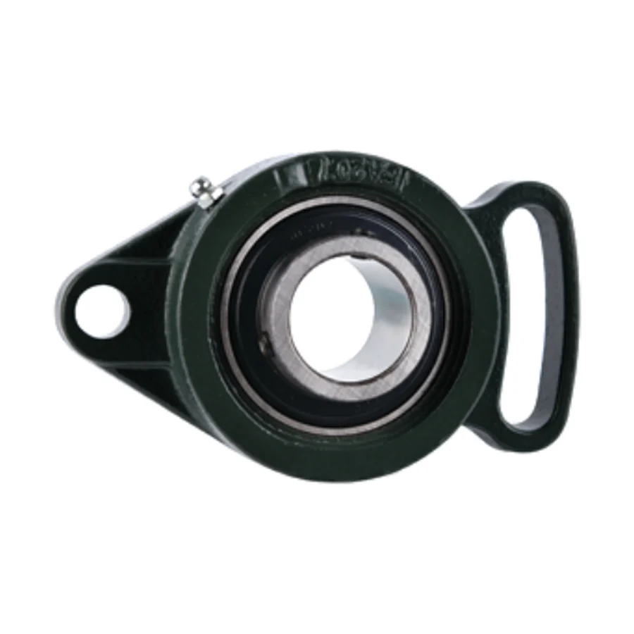
UCFA200 Series Adjustable Flange Bearing Units — Angular Adjustment After Installation
The UCFA200 series is the adjustable-flange variant of the standard oval two-bolt flange bearing unit. Where the UCFL200 has round clearance bolt holes that fix the housing in position once bolted down, the UCFA200 uses slotted bolt holes that allow the entire housing to be rotated about the shaft axis by a defined angular range after the mounting bolts are partially tightened. This means the bearing centreline can be fine-tuned to match the shaft axis without removing the bearing from the shaft, re-drilling the mounting panel, or adding shimming plates. Once the correct angular position is reached, the bolts are fully tightened to lock the housing in place.
The UCFA200 is the correct choice when the shaft and the machine frame panel are not precisely perpendicular — a common condition in field-erected structures, welded fabrications, and retrofits where the mounting panel is not machined. In these situations a standard oval flange (UCFL200) would require the installer to shim or re-drill to achieve alignment; the UCFA200 accommodates the angular offset through the slotted adjustment without any metalwork.
Adjustable Flange Geometry — N1, N2, and the Slot
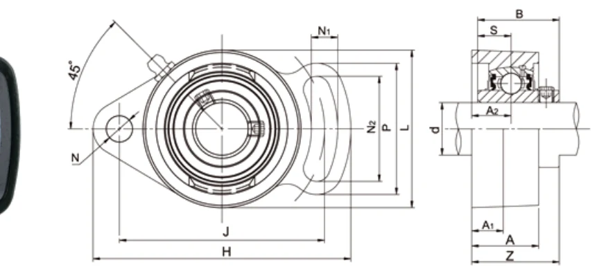
The UCFA200 specification table includes two bolt-related dimensions not present in the UCFL200: N1 and N2. N is the bolt hole diameter (same meaning as in UCFL200). N1 is the slot width — the narrow dimension of the slotted hole that the bolt shank passes through. N2 is the slot length — the arc length over which the housing can travel as it is rotated about the shaft axis. The ratio of N2 to the bolt circle radius J/2 gives the angular adjustment range available: at UCFA205 (J=98 mm, N2=51 mm), the arc is approximately ±30° from the nominal position, providing substantial alignment correction capability without any machining.
P is the bolt hole pitch — the centre-to-centre distance between the two slotted holes along the oval housing's long axis. H is the centreline height from the mounting face to the shaft centreline, identical in meaning to the UCFL200 H.
Key Features
↻
Slotted Bolt Holes for Angular Adjustment
N1 (slot width) × N2 (slot length) holes replace the round clearance holes of UCFL200. Housing rotates about the shaft axis after partial bolt tightening to correct angular misalignment between shaft and panel — no re-drilling required.
🔧
Setscrew Locking — UC Insert
Dual 120° setscrew, wide inner ring UC insert, self-aligning spherical OD. Same bore suffix system and insert procedure as UCFL200. Metric and inch bore options.
◯
Oval Two-Bolt Housing Profile
Same outer oval profile as UCFL200. H, J, A, B dimensions are similar to UCFL200 equivalents; verify from UCFA200 table as slot geometry adjusts some values.
✅
Field Alignment Without Metalwork
Correct shaft-to-panel angular offset without shimming, re-drilling, or machining. Particularly valuable in field-erected steel structures, welded frames, and retrofit installations where the panel face angle cannot be guaranteed.
💧
End Caps Available
SM (closed one side) or S (open) pressed steel end caps available on request.
▭
Solid Base Option
Hollow base standard. Solid base (SB) available on request.
Full Dimensional Specifications
| Unit No. | d mm | d inch | H mm | J mm | A2 mm | A1 mm | A mm | N mm | N1 mm | N2 mm | L mm | P mm | B mm | S mm | Z mm | Bolt | kg |
|---|---|---|---|---|---|---|---|---|---|---|---|---|---|---|---|---|---|
| UCFA201 / 201-8 | 12 | 1/2 | 98 | 78 | 15 | 12 | 25.5 | 10 | 10 | 40 | 60 | 50 | 31 | 12.7 | 33.3 | M8 | 0.53 |
| UCFA202 / 202-9/10 | 15 | 9/16~5/8 | 98 | 78 | 15 | 12 | 25.5 | 10 | 10 | 40 | 60 | 50 | 31 | 12.7 | 33.3 | M8 | 0.49 |
| UCFA203 / 203-11 | 17 | 11/16 | 98 | 78 | 15 | 12 | 25.5 | 10 | 10 | 40 | 60 | 50 | 31 | 12.7 | 33.3 | M8 | 0.48 |
| UCFA204 / 204-12 | 20 | 3/4 | 98 | 78 | 15 | 12 | 25.5 | 10 | 10 | 40 | 60 | 50 | 31 | 12.7 | 33.3 | M8 | 0.46 |
| UCFA205 / 205-14~16 | 25 | 7/8~1 | 125 | 98 | 16 | 14 | 27 | 12 | 13 | 51 | 70 | 65 | 34.1 | 14.3 | 35.8 | M10 | 0.69 |
| UCFA206 / 206-17~20 | 30 | 1-1/16~1-1/4 | 142 | 117 | 18 | 14 | 31 | 12 | 13 | 58 | 83 | 72 | 38.1 | 15.9 | 40.2 | M10 | 1.00 |
| UCFA207 / 207-20~23 | 35 | 1-1/4~1-7/16 | 154 | 130 | 19 | 16 | 34 | 15 | 15 | 66 | 95 | 82 | 42.9 | 17.5 | 44.4 | M12 | 1.50 |
| UCFA208 / 208-24/25 | 40 | 1-1/2~1-9/16 | 172 | 144 | 21 | 16 | 38 | 15 | 15 | 71 | 105 | 87 | 49.2 | 19.0 | 51.2 | M12 | 1.80 |
| UCFA209 / 209-26~28 | 45 | 1-5/8~1-3/4 | 180 | 148 | 22 | 18 | 40 | 15 | 15 | 72 | 110 | 90 | 49.2 | 19.0 | 52.2 | M14 | 2.10 |
| UCFA210 / 210-30~32 | 50 | 1-7/8~2 | 190 | 157 | 22 | 18 | 40 | 15 | 15 | 76 | 115 | 94 | 51.6 | 19.0 | 54.6 | M14 | 2.30 |
| UCFA211 / 211-32~35 | 55 | 2~2-3/16 | 216 | 184 | 25 | 20 | 43 | 16 | 17 | 86 | 132 | 104 | 55.6 | 22.2 | 58.4 | M14 | 3.60 |
→ Scroll horizontally to view all columns. Catalogue dimensions for reference only — engineering drawings required before order.
N = bolt hole diameter. N1 = slot width. N2 = slot arc length (determines angular adjustment range). P = bolt hole pitch (centre-to-centre). H = centreline height. Solid base: suffix SB. End caps: SM/S prefix.
UCFA200 vs UCFL200 — When to Choose the Adjustable Flange
Use UCFL200 when the mounting panel is machined or otherwise guaranteed perpendicular to the shaft, or when bolt position is fixed and alignment is achieved by shaft preparation. Use UCFA200 when the panel is field-welded, cast, or otherwise not precisely perpendicular — the slotted holes let the installer rotate the housing to the correct angular position before final tightening, removing a machining step from the installation procedure.
The UC insert bearing in the UCFA200 already accommodates up to 2° of static misalignment through its spherical OD. The slot adjustment is for larger initial angular offsets that would place the bearing outside its self-alignment range if the housing were bolted in the nominal panel orientation. The two capabilities work together: the slot corrects gross installation angle; the spherical insert absorbs residual thermal and dynamic misalignment in service.
Applications
🏛
Field-Erected Steel Structure Supports
Shaft supports on field-erected conveyor gantries, process plant walkways, and structural steel frames where the bearing panel face angle cannot be controlled to machined tolerances and standard round-hole flanges require shimming to achieve acceptable alignment.
⚙
Welded Fabrication Frame Supports
Bearing positions on welded machine frames where heat distortion and fabrication tolerance accumulation result in panel face angles that deviate from nominal, and re-machining the panel is not practical after welding.
🌿
Agricultural Implement Retrofit Positions
Shaft supports on agricultural implements where worn or deformed frame panels have shifted the bearing mounting face angle and the slot adjustment allows re-alignment without frame repair.
🔄
Retrofit & Replacement on Non-Perpendicular Panels
Any retrofit bearing position where the original bearing has been removed and measurement shows the panel face is not perpendicular to the shaft — UCFA200 corrects the offset at installation without requiring panel metalwork.
▶
Conveyor Drive & Tail Shaft Field Supports
Drive and tail pulley shaft oval flange supports on field-assembled conveyor structures where frame fabrication tolerances make a fixed-position oval flange difficult to align without an adjustable slot.
📦
Compact Machine Frames with Accumulated Tolerance
Shaft supports on compact machines where tolerance stackup across multiple welded or bolted joints results in a panel face angle offset that the UCFA200 slot absorbs without requiring frame modification.
📦 MOQ & Order Information
- Standard parts: quantity-based MOQ applies per model number.
- High-value / large items: minimum order by USD order value.
- New-client samples: 1–5 pcs available at sample price for first-time buyers.
- Multi-model combines: aggregate orders of USD 1,500 or more across models accepted.
- Special materials / processes: subject to process MOQ — confirm at inquiry stage.
- Retail (1–2 pcs): not accepted. Minimum sample order is 1–5 pcs at sample pricing.
Engineering drawings must be submitted and approved before order confirmation. Catalogue dimensions are for reference only.
Frequently Asked Questions
What is the difference between UCFA200 and UCFL200?
UCFL200 = round bolt holes, fixed position. UCFA200 = slotted bolt holes (N1×N2), angular adjustment about shaft axis after partial tightening. Same UC insert and setscrew locking in both.
What do N1 and N2 mean?
N = bolt hole diameter. N1 = slot width. N2 = slot arc length (determines angular adjustment range ≈ N2 ÷ (J/2) in radians).
How much angular adjustment?
~±30° for UCFA205 (N2=51 mm, J=98 mm). Other sizes proportionally similar. Check N2 value for exact size.
Can I use UCFA200 on a reversing drive?
Yes — setscrew is bidirectional. For high-speed reversing, standard UCFL200 guidance applies.
What is the MOQ?
Standard parts: quantity-based MOQ. Samples 1–5 pcs. Multi-model from USD 1,500. Retail 1–2 pcs not accepted.
Request a Quote for UCFA200 Series
Provide shaft diameter, bore type (metric or inch), angular offset of the mounting panel if known, and quantity. Contact us.