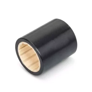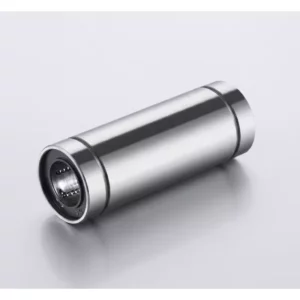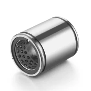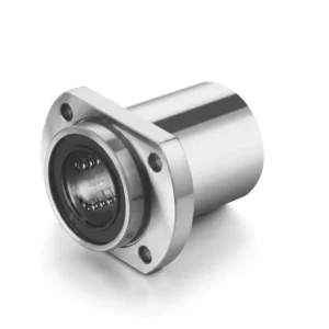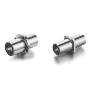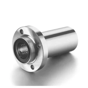
UEFC200 Series Flange Cartridge Bearing Units
UEFC200 is aimed at applications that need a round flange cartridge housing but prefer a concentric shaft-locking arrangement. That distinction is more important than appearance: the housing may share a familiar four-bolt pattern with other FC units, yet the way the insert grips the shaft changes installation practice and replacement compatibility.
The published series covers 20-60 mm shafts. This makes UEFC200 a more focused range than the broad UCFC family, and it should be selected from the locking requirement outward: first confirm that concentric retention is wanted, then verify bore, pilot, bolt pattern and axial envelope.
For a wider housing comparison, browse the bearings range before finalising the mounting style.
A cartridge unit selected from the shaft outward
Concentric retention
The insert uses a concentric locking method, providing a different shaft interface from setscrew and eccentric-collar alternatives.
Compact four-bolt mounting
A round cast-iron flange keeps the bearing centre close to the supporting face.
Focused metric size range
Catalogue sizes cover 20, 25, 30, 35, 40, 45, 50, 55 and 60 mm shafts.
Dedicated B1 dimension
The catalogue identifies B1 among the relevant insert dimensions, helping distinguish this locking configuration during cross-reference work.
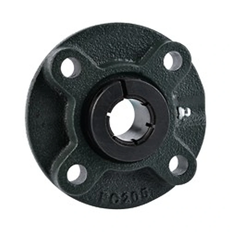
UEFC200 dimensional checklist
Use the product drawing as the final dimensional authority. The points below are practical filters that help narrow the correct model before a full drawing comparison.
Do not substitute solely on bore and flange size. The existing shaft retention method must be part of the specification.
Check the published B1, S and related axial dimensions against nearby shoulders, spacers and drive components.
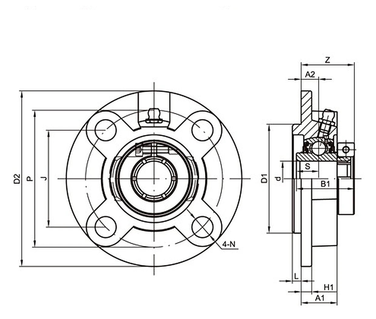
Verify D2, P, J, A2 and bolt size on the drawing before treating a similar-looking cartridge as interchangeable.
Consider how the bearing is accessed once guards, pulleys or couplings are installed, not only when the frame is bare.
UEFC200 published technical range
The table below keeps the catalogue values used for this series. Use the model-specific drawing for the final interchange decision; dimensions and suffixes can vary inside a family.
| Specification point | UEFC200 catalogue data |
|---|---|
| Series / model family | UEFC204 to UEFC212 |
| Duty class | Standard duty |
| Locking / bearing mounting | Concentric locking |
| Published shaft range | 20-60 mm |
| Published metric / inch options | 20, 25, 30, 35, 40, 45, 50, 55, 60 mm |
| Housing / mounting style | 4-bolt round flange cartridge housing |
| Housing construction | Cast iron |
| Catalog dimensional fields | D2, P, J, A2, N, L, H1, A1, D1, B1, S, Z, bolt size and weight |
| Published unit weight | 0.75-5.33 kg |
Applications that benefit from a centred locking approach
These are application patterns where the housing concept is commonly considered. Final suitability still depends on load, speed, alignment, environment and the machine designer’s requirements.
Precision-oriented OEM assemblies
Useful where the equipment designer has standardised on a concentric locking insert within a round flange housing.
Roller support plates
A four-bolt face mount works neatly on fabricated side plates and modular roller stations.
Compact drive modules
The cartridge format can support shafts where a pedestal would interfere with belts, covers or adjacent mechanisms.
Maintenance conversions with engineering approval
UEFC can be evaluated when changing from another locking method, provided shaft condition and dimensional compatibility are checked as a complete system.
UEFC200 in the FC family
UEFC200 is the FC-family option to consider when concentric locking is required. UCFC200 covers a wider shaft range with setscrew retention, NAFC200 uses eccentric locking, and UKFC200+H is based on an adapter sleeve. The correct family depends on the shaft connection as much as the mounting pattern.
Commissioning a concentric-lock insert
Use the approved concentric-lock installation procedure for the insert rather than applying setscrew or eccentric-collar habits.
Clean the shaft and remove raised damage before the insert is positioned.
If the flange will not seat naturally, correct the mounting face instead of pulling it into position with the bolts.
Store UEFC as a distinct spare code so future maintenance does not receive a visually similar but different insert type.
Send the machine details for a model check
For UEFC200, send the existing model marking, shaft diameter, mounting dimensions and a photo of the bearing position. GBC can review the information against the published series before quotation. Email: sales@australia-drive.com.