
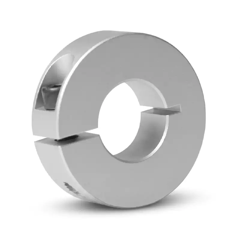
GBC-SCS18 Aluminum Clamp Type Shaft Collar – 18mm Bore
The GBC-SCS18 aluminum clamp-type shaft collar fits 18 mm bore shafts. OD steps up to 40 mm, face width 12 mm, M5 screw, optional 6 mm keyway. Engineered for textile winding shafts, light worm gearbox outputs, and industrial fan hubs subject to sustained vibration and cyclic axial thrust.
MOQ: 50 pcs. Minimum order value USD 1,500; mixed orders and trial quantities welcome.
18mm Bore Aluminum Clamp Shaft Collar – Textile Machinery & Light Gearbox Output Shaft Location
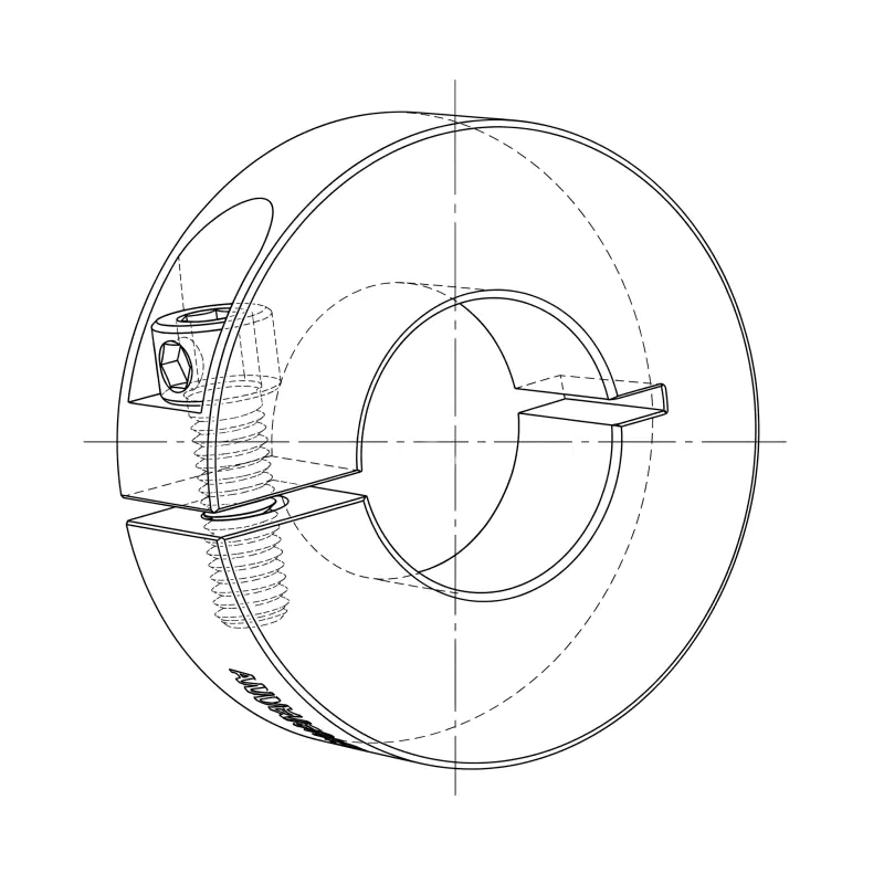
| Parameter | Value | Note |
|---|---|---|
| SKU / Model | GBC-SCS18 | GBC SCS Series |
| Bore Diameter (d) | 18 mm | Shaft tolerance h6 recommended |
| Outer Diameter (D) | 40 mm | |
| Face Width (B) | 12 mm | |
| Clamping Screw | M5 socket-head cap screw | 5 mm hex key required |
| Slot Width (W) | 1.5 mm | Enables radial flex for clamping |
| Keyway Width (K) | 6 mm | Standard: plain bore; keyway optional on request |
| Shaft Tolerance | 18.000 / 17.989 mm | ISO 286 h6 |
| Material | Aluminium alloy | Anodized finish available on request |
| MOQ | 100 pcs | Custom engineering drawings accepted |
Product Overview
The GBC-SCS18 introduces the first OD step change in the mid-range SCS series, growing from 35 mm to 40 mm outer diameter while retaining the 12 mm face width and M5 clamping screw. This enlarged OD delivers a meaningfully wider clamping band around the 18 mm bore, improving axial holding force and resistance to micro-rotation under cyclic radial loads — a requirement in textile winding machines, light-duty worm gearbox outputs, and industrial fan shaft end-stops where sustained vibration from unbalanced rotating masses is a routine challenge. The 6 mm keyway option steps up from the 5 mm key used at smaller bores, consistent with DIN 6885 key tables for 18 mm shafts and enabling direct coupling to sprockets, pulleys, and cams without secondary locking features.
Key Features
Shaft Surface Protection
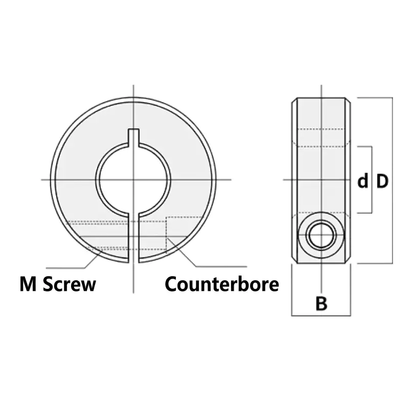
The split-clamp principle spreads clamping force uniformly across the full bore circumference, preventing the point indentation and fretting corrosion that set-screw collars create at the contact point. The shaft remains undamaged and fully repositionable throughout the product's service life.
M5 High-Torque Clamping
The M5 socket-head cap screw provides a proof-load capacity approximately 60% higher than the M4 screws used in smaller SCS collars. This increase in clamping force is matched to the larger bore and OD at this size range, ensuring reliable retention under sustained bidirectional axial loading.
Dual Axial-Location Function
A single collar acts as a positive end-stop against a bearing or housing shoulder. A pair of collars sandwiches any shaft-mounted component at a freely adjustable position — a versatile alternative to machined shaft steps that eliminates re-machining costs when axial positions need to change.
Lightweight Aluminium Alloy Body
Aluminium alloy construction keeps collar mass below 30 g for all bore sizes in the 18 mm OD range, minimising the rotational inertia penalty in dynamic drive assemblies and the static load penalty on vertically mounted shafts.
6 mm Keyway Option for Torque Locking
A standard 6 mm DIN 6885 keyway can be broached on request, enabling the collar to transmit rotational torque simultaneously with axial positioning. Specify at order — default supply is plain bore.
Typical Application Scenarios
Textile Winding & Spinning Machinery
Warp-beam shafts in weaving looms and bobbin-winding spindle assemblies standardise on 18 mm shaft diameters. The SCS18 positions the beam end-flanges and provides a positive axial stop that prevents flange walk during the tension cycling inherent to warp-thread shedding motions, reducing warp-break rates and downtime.
Light Worm Gearbox Output Shafts
Compact worm gearboxes in packaging line indexers and gate-drive mechanisms frequently output on 18 mm shafts. The SCS18 collar locates the driven sprocket or cam disc at the correct axial position relative to the chain or follower track, maintaining engagement geometry as the gearbox heats to operating temperature and the shaft grows axially.
Industrial Fan Blade Hubs
Axial cooling fans in switchgear cabinets and motor-control enclosures mount blade hubs on 18 mm motor-extension shafts. The SCS18 retains the hub against the motor end-shield bearing face, preventing hub walk driven by aerodynamic thrust forces without requiring a machined shaft step or retaining ring groove.
Dimensional Guide & Shaft Fit Specification
The three principal dimensions — bore d = 18 mm, outer diameter D = 40 mm, and face width B = 12 mm — define the spatial envelope of the collar in an assembly. The slot width W = 1.5 mm runs the full face width and is the feature that allows the collar to flex radially as the M5 screw closes the gap. Specify the mating shaft to ISO 286 h6 tolerance (18.000 / 17.989 mm) for the optimal combination of sliding fit before clamping and maximum retention force after clamping.
GBC accepts custom orders for alternative bore tolerances (H7, js6), reduced OD profiles to clear adjacent components, extended face widths for higher axial holding force, and surface treatments including natural anodize, hard anodize (25 µm), and electroless nickel plating. Submit your engineering drawing via the contact page for a fast quotation.
Model Selection Guide
For 16 mm servo and ball-screw shafts, the GBC-SCS16 at 35 mm OD is the appropriate choice. For the most versatile mid-range size at 20 mm bore — compatible with the widest range of motor, gearbox, and drive components — the GBC-SCS20 shares the 40 mm OD and 12 mm face width.
| Model | Bore | Relation |
|---|---|---|
| GBC-SCS16 | 16mm | ← Smaller |
| GBC-SCS18 | 18 mm | ◀ Current |
| GBC-SCS20 | 20mm | → Larger |
Installation Procedure
- Prepare the shaft: Clean and degrease the shaft in the clamping zone. Verify diameter within h6 tolerance (18.000 / 17.989 mm). Remove any burrs or nicks with a fine file.
- Slide and position: Slide the GBC-SCS18 onto the shaft to the required axial location. Use a calibrated depth gauge or a pre-machined spacer as a reference for repeatable positioning.
- Clamp progressively: Using a 5 mm hex key, tighten the M5 screw in two or three incremental steps, checking axial position after each step to correct any settling. Torque M5 screw to 4.5 N·m. In fan and vibrating-machinery applications, apply medium-strength threadlocker (Loctite 243 or equivalent) and re-verify torque after 24 hours of operation as thermal cycling can relax the initial clamp preload.
- Load test: Apply the expected axial service load (manually or via the driven machine) and confirm zero collar movement. For vibrating or cyclic-load applications, re-verify screw torque after the first full operating shift.
Frequently Asked Questions
Why does the OD increase from 35mm to 40mm at the SCS18 compared to SCS16?
How do I calculate the axial spacing between two SCS18 collars to clamp a component with defined length?
Can the SCS18 6mm keyway be broached in-house or must it be ordered from GBC?
Related Products
Explore adjacent sizes and related components in the GBC range:
- GBC-SCS16 – 16mm bore aluminum clamp shaft collar — smaller bore for finer shaft diameters
- GBC-SCS20 – 20mm bore aluminum clamp shaft collar — next size up for higher axial capacity
- Browse the full GBC SCS Shaft Collar series — available bore sizes from 6 mm to 60 mm
Get a Quote or Submit Your Drawing
Minimum order quantity is 100 pcs. Custom bore tolerances, keyway options, extended face widths, and surface treatments are available. Supply your detailed engineering drawing for an accurate quotation from the GBC team.
The GBC-SCS18 aluminum clamp-type shaft collar fits 18 mm bore shafts. OD steps up to 40 mm, face width 12 mm, M5 screw, optional 6 mm keyway. Engineered for textile winding shafts, light worm gearbox outputs, and industrial fan hubs subject to sustained vibration and cyclic axial thrust.
MOQ: 50 pcs. Minimum order value USD 1,500; mixed orders and trial quantities welcome.
Related products
-
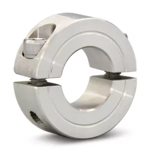
GBC-SCS35 Aluminum Clamp Type Shaft Collar – 35mm Bore
-
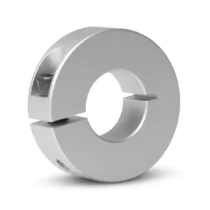
GBC-SCS10 Aluminum Clamp Type Shaft Collar – 10mm Bore
-
GBC-SCS25 Aluminum Clamp Type Shaft Collar – 25mm Bore
-
GBC-SCS45 Aluminum Clamp Type Shaft Collar – 45mm Bore
-
GBC-SCS08 Aluminum Clamp Type Shaft Collar – 8mm Bore
-
GBC-SCS60 Aluminum Clamp Type Shaft Collar – 60mm Bore