
Shaft Collars
Precision clamp-type shaft collars in aluminium alloy — from 6 mm to 60 mm bore. Zero shaft damage, field-adjustable, and available with optional keyway for simultaneous axial and rotational locking.
A shaft collar is one of the most fundamental positioning components in any rotating machine. Fitted to a shaft and secured by a clamping screw, it creates a precise axial stop that holds bearings, sprockets, cams, and coupling hubs at defined positions along the shaft — without threading, welding, or machining the shaft itself.
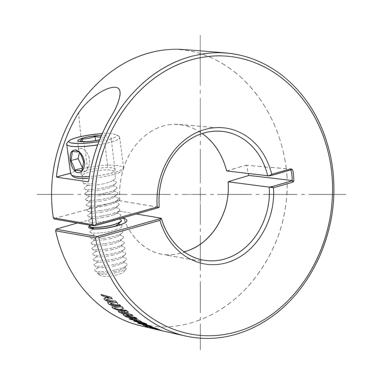
The GBC SCS series uses a split-clamp design: a single longitudinal slot allows the collar bore to flex radially as the clamping screw is tightened, distributing clamping force uniformly around the full shaft circumference. This eliminates the stress concentration and surface indentation associated with set-screw collars, preserving shaft surface integrity across repeated repositioning cycles.
All collars in the SCS range are machined from aluminium alloy, delivering the strength-to-weight ratio required for dynamic drive assemblies while keeping rotational inertia additions below the threshold that affects system performance. Keyway options follow DIN 6885 Form A for each bore size, enabling the collar to function simultaneously as an axial locator and a full-torque rotational coupling element.
MOQ is 100 pcs per model. Custom bore tolerances, extended face widths, anodized finishes, and steel variants are available — supply your engineering drawing via the GBC enquiry page for a fast quotation.
Browse by Bore Size Group
Select the bore group that matches your shaft diameter. Each size range shares a common OD and clamping screw size, making cross-specification straightforward.
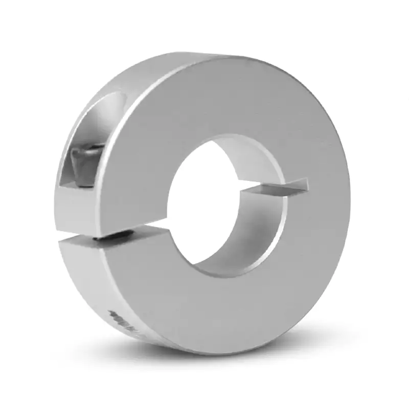
Small Bore — 6 mm to 13 mm
Ultra-compact collars for precision instruments, miniature robotics, CNC accessories, and 3D printer drive shafts. M4 clamping screw. OD range 20–30 mm. Keyway available from 10 mm bore upward (3–4 mm width).
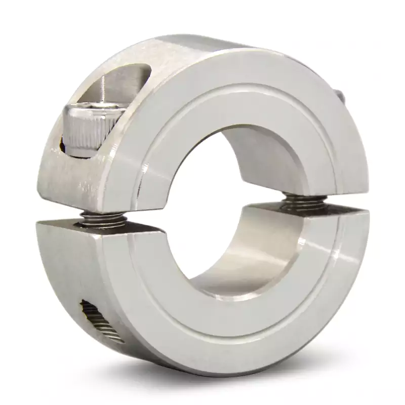
Standard Bore — 14 mm to 20 mm
The most widely specified bore range, covering IEC servo motor shafts, SFU ball-screw journals, belt conveyor rollers, and printing press ink-train shafts. M5 clamping screw. OD range 35–40 mm. Keyway 5–6 mm.
Medium-Heavy Bore — 22 mm to 35 mm
Industrial-grade collars for helical gearbox outputs, agricultural baler drives, heavy belt conveyors, and mining auxiliary shafts. M5 to M6 clamping screw. OD range 45–60 mm. Face width 12–15 mm. Keyway 6–10 mm.
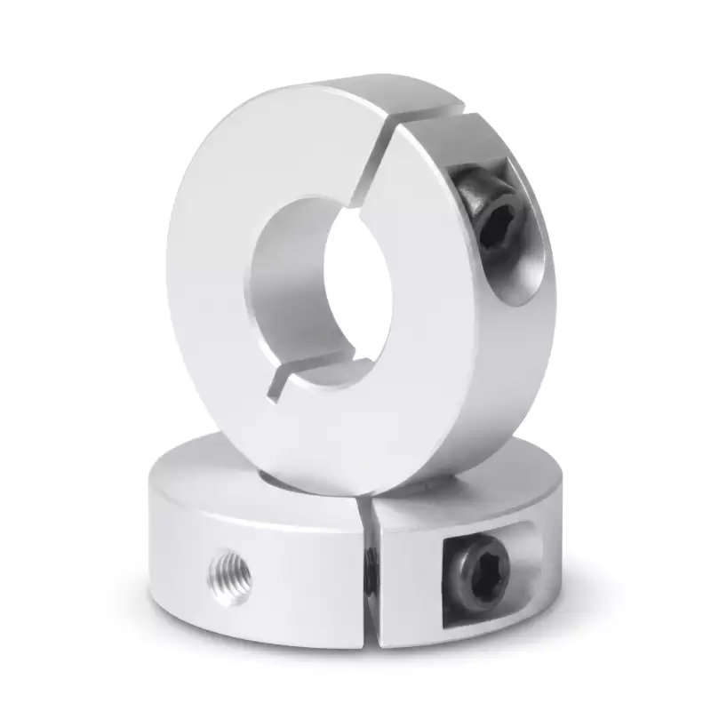
Large Bore — 40 mm to 60 mm
Heavy-industrial collars for large gearbox outputs, rotary table drives, ship auxiliary machinery, rolling mill shafts, and rotary kiln drives. M8 to M10 clamping screw up to 35 N·m. OD range 70–95 mm. Face width 18–22 mm. Keyway 12–18 mm.
Why Choose a Clamp-Type Shaft Collar
The split-clamp design offers measurable engineering advantages over set-screw and welded alternatives across a wide range of shaft diameters and duty types.
No Shaft Surface Damage
Clamping force is distributed uniformly around the full shaft circumference. Set-screw indentation, fretting corrosion, and fatigue-initiating stress concentrations are eliminated, preserving ground and hard-chrome shaft surfaces for the full equipment service life.
Field-Adjustable Position
Axial position can be changed during commissioning or maintenance using only a hex key — no shaft removal, no bearing housing disassembly, no re-machining. This flexibility is particularly valuable when bearing pre-load or component lateral position must be optimised after initial assembly.
Dual Axial-Location Modes
A single collar acts as a positive end-stop against a bearing or housing shoulder. A pair of collars sandwiches any shaft-mounted component at a freely adjustable position — effectively replacing machined shaft shoulders without the associated lead time and cost.
Optional Keyway for Torque Locking
All SCS collars from 10 mm bore upward are available with a DIN 6885 Form A keyway, enabling the collar to transmit rotational torque simultaneously with axial positioning. One component replaces two — reducing part count, assembly time, and the risk of positional errors between separate locking and locating elements.
Lightweight Aluminium Construction
Aluminium alloy keeps collar mass well below equivalent steel or cast iron designs, minimising the rotational inertia added to dynamic drive assemblies. At bore sizes below 30 mm, the collar mass contribution to total shaft inertia is typically below 0.5%.
Custom Specifications Available
GBC supplies hard-anodized (25 um), electroless nickel-plated, and 316L stainless steel variants for corrosive, marine, and food-grade environments. Twin-screw configurations, extended face widths, and reduced-OD profiles are available. Provide your engineering drawing for a tailored quotation.
Application-Based Selection Guide
Match your application type and shaft diameter to the recommended GBC SCS collar model using the table below.
| Application Type | Typical Shaft Diameter | Recommended Model | Key Specification |
|---|---|---|---|
| Precision instrument / optical stage | 6–8 mm | SCS06 / SCS08 | OD 20–30 mm, M4, ultra-compact |
| CNC router / 3D printer extruder | 10 mm | SCS10 | OD 30 mm, M4, 3 mm keyway option |
| Ball screw fixed-end support (SFU1605) | 16 mm | SCS16 | OD 35 mm, M5, 5 mm keyway |
| IEC 90-frame motor output / SFU2005 | 20 mm | SCS20 | OD 40 mm, M5, 6 mm keyway |
| Helical gearbox output / conveyor pulley | 25 mm | SCS25 | OD 45 mm, M5, 8 mm keyway |
| Agricultural baler / heavy belt conveyor | 30 mm | SCS30 | OD 55 mm, M6, 8 mm keyway |
| Large gearbox output / rotary table drive | 40 mm | SCS40 | OD 70 mm, M8, 12 mm keyway |
| Ship auxiliary / large industrial fan hub | 45 mm | SCS45 | OD 80 mm, M10, 14 mm keyway |
| Large pump / rolling mill roller shaft | 50 mm | SCS50 | OD 85 mm, M10, 3 mm wide slot |
| Crusher / rotary kiln gearbox output | 60 mm | SCS60 | OD 95 mm, M10, 18 mm keyway |
Installation Overview
All GBC SCS clamp shaft collars install with a single hex key in four steps. No adhesive, no shaft modification, and no special tooling required for bore sizes up to 35 mm.
Verify Shaft Diameter
Confirm the shaft diameter falls within ISO 286 h6 tolerance using a calibrated micrometer. Degrease the clamping zone and remove burrs.
Slide and Position
Slide the collar onto the shaft to the required axial location. Use a depth gauge or spacer as a reference for repeatable placement.
Tighten Progressively
Tighten the clamping screw in three incremental steps — 30%, 70%, then full rated torque — checking position after each step. Apply threadlocker for vibration environments.
Verify Under Load
Apply the expected axial service load and confirm zero collar movement. Re-check torque after the first full operating shift for vibrating or cyclic-load applications.
Detailed installation torque values and shaft tolerance specifications are listed on each individual product page. For assemblies with bore sizes above 40 mm, a calibrated torque wrench with a hex-bit socket is mandatory — hand-held T-bar keys cannot reliably achieve the rated M8 and M10 clamping torques required at these bore sizes.
Frequently Asked Questions
Common technical and ordering questions about GBC SCS series shaft collars.
What is the difference between a clamp-type and a set-screw shaft collar?
How do I select the correct bore size if my shaft is at the boundary between two models?
Do all SCS collars include a keyway as standard?
What shaft surface finish and tolerance is required for reliable clamping?
Can GBC supply shaft collars in stainless steel or with food-grade surface treatment?
What is the minimum order quantity, and are custom dimensions available?
Ready to Specify Your Shaft Collar?
Browse individual model pages for full dimensional data and application guidance, or contact GBC with your engineering drawing for a custom quotation. MOQ 100 pcs. Fast turnaround on standard aluminium SCS series.
Request a Quote →