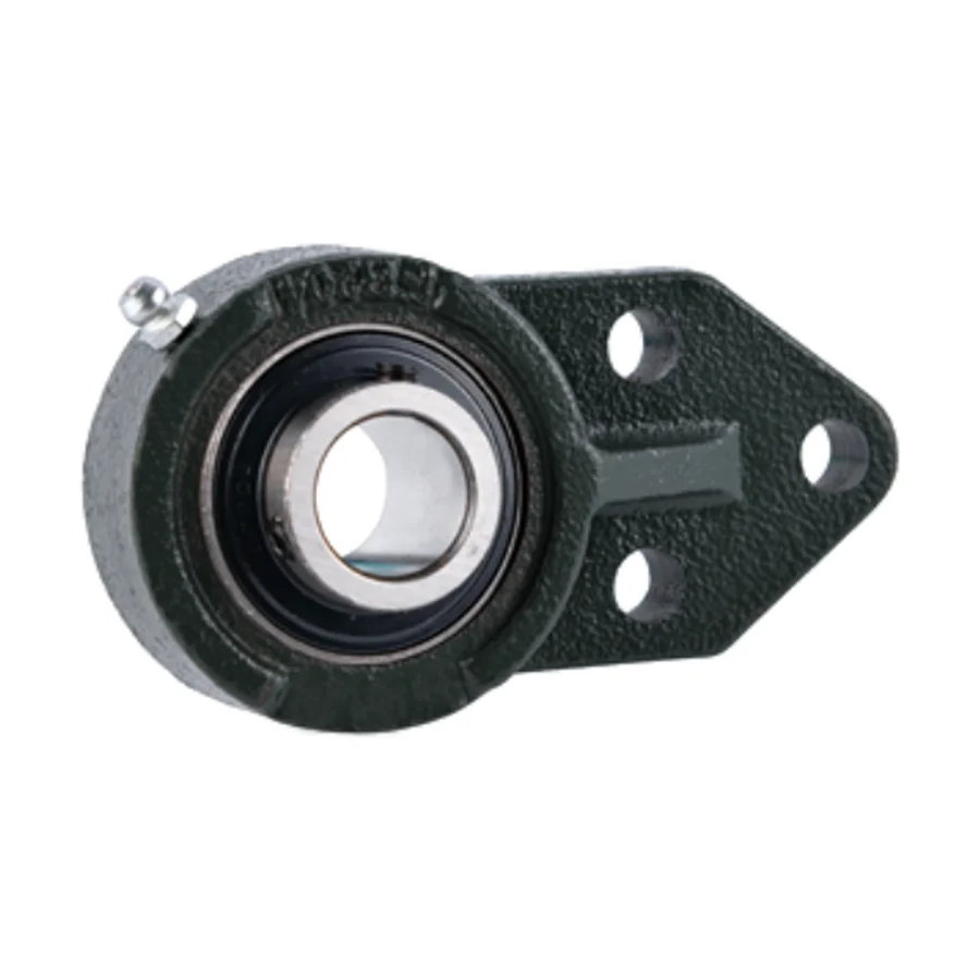
UCFB200 & UCFB200A Series 3-Bolt Flange Bearing Units — Flange Bracket, Setscrew Locking
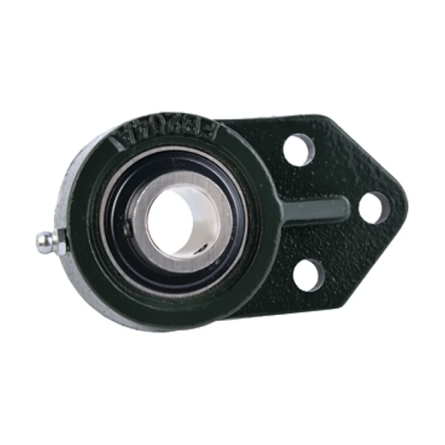
The UCFB200 series introduces the three-bolt flange bracket geometry — a housing profile that mounts at 45° to the shaft axis, with bolt holes positioned at one top-centre and two lower corners. This configuration is distinct from both the square four-bolt flange (UCF200) and the oval two-bolt flange (UCFL200): the three-bolt bracket provides more resistance to rotation about the shaft axis than a two-bolt design, while requiring less machine frame material than a four-bolt square flange. It is the standard choice for bracket-mounting where space permits only three fastener positions, or where the 45° bracket orientation allows a bearing to be fitted in a corner location that neither a square nor oval flange could access.
UCFB200 uses metric bolt hole dimensions throughout. UCFB200A uses inch-based housing dimensions — all J, j, A2, A1, A, L, P values are in inch-fraction equivalents — for direct replacement of inch-standard 3-bolt bracket bearings in North American and British Commonwealth equipment.
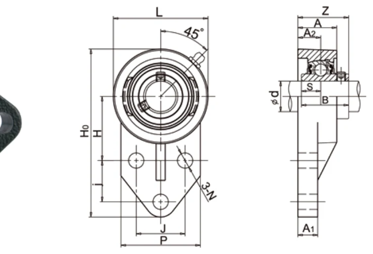
Three-Bolt Bracket Geometry — H0 and the Mounting Stance
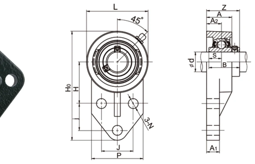
The key geometric parameter of the UCFB200 is H0 — the distance from the mounting face to the shaft centreline. This dimension is larger than the equivalent H of a two-bolt oval flange (UCFL200) at the same bore size, because the bracket body must clear the three bolt positions. The j dimension in the specification table is the bolt hole pitch radius at the base of the bracket — the two lower bolts are at radius j from the bracket centreline, while the top-centre bolt is at a higher position on the bracket. The 45° bracket face orientation means the H0 measurement is taken perpendicular to this face.
Key Features
△
Three-Bolt Bracket at 45°
One top-centre and two lower-corner bolt positions. More rotation resistance than two-bolt oval flange, less frame material than four-bolt square flange. Suits corner and bracket mounting positions.
🔧
Setscrew Locking
Dual 120° setscrew retention — same UC insert and bore suffix system as UCF200 and UCFL200. Metric and inch bore options.
🌎
Metric (UCFB200) and Inch (UCFB200A)
UCFB200 metric bolt holes and housing dimensions. UCFB200A inch-based housing dimensions for direct replacement of inch-standard 3-bolt brackets. Same insert bearing in both.
↔
Self-Aligning UC Insert
Wide inner ring, spherical OD, 2° misalignment compensation. Axial float capacity.
💧
End Caps Available
SM (closed) or S (open) pressed steel end caps available on request.
✅
GB / ISO / ANSI / JIS Compliant
UCFB200A inch dimensions cover ANSI and BS interchangeability for legacy inch-standard bracket bearings.
UCFB200 Metric Series Specifications
| Unit No. | d mm | d inch | H0 mm | H mm | J mm | j mm | A2 mm | A1 mm | A mm | N mm | L mm | P mm | B mm | S mm | Z mm | Bolt | kg |
|---|---|---|---|---|---|---|---|---|---|---|---|---|---|---|---|---|---|
| UCFB201~204 / -8~204-12 | 12~20 | 1/2~3/4 | 110 | 42 | 32 | 27 | 15 | 13 | 25.5 | 10 | 62 | 52 | 31 | 12.7 | 33.3 | M8 | 0.57~0.62 |
| UCFB205 / 205-14~16 | 25 | 7/8~1 | 116 | 45 | 34 | 27 | 16 | 13 | 27 | 10 | 68 | 56 | 34.1 | 14.3 | 35.7 | M8 | 0.69 |
| UCFB206 / 206-17~20 | 30 | 1-1/16~1-1/4 | 130 | 50 | 40 | 29 | 18 | 13 | 31 | 10 | 78 | 65 | 38.1 | 15.9 | 40.2 | M8 | 0.93 |
| UCFB207 / 207-20~23 | 35 | 1-1/4~1-7/16 | 144 | 55 | 46 | 32 | 19 | 15 | 34 | 10 | 90 | 70 | 42.9 | 17.5 | 44.4 | M8 | 1.30 |
| UCFB208 / 208-24/25 | 40 | 1-1/2~1-9/16 | 164 | 60 | 50 | 41 | 21 | 16 | 36 | 12 | 100 | 78 | 49.2 | 19.0 | 51.2 | M10 | 1.80 |
| UCFB209 / 209-26~28 | 45 | 1-5/8~1-3/4 | 174 | 65 | 54 | 43 | 22 | 18 | 38 | 12 | 106 | 80 | 49.2 | 19.0 | 52.2 | M10 | 2.00 |
| UCFB210 / 210-30~32 | 50 | 1-7/8~2 | 184 | 68 | 58 | 46 | 22 | 18 | 40 | 12 | 112 | 86 | 51.6 | 19.0 | 54.6 | M10 | 2.30 |
→ Scroll horizontally to view all columns. Catalogue dimensions for reference only — engineering drawings required before order.
UCFB200A Inch-Based Housing Specifications
| Unit No. | d mm | d inch | H0 mm | H mm | J mm | j mm | A2 mm | A1 mm | A mm | N mm | L mm | P mm | B mm | S mm | Z mm | Bolt | kg |
|---|---|---|---|---|---|---|---|---|---|---|---|---|---|---|---|---|---|
| UCFB201A~204A / -8A~204-12A | 12~20 | 1/2~3/4 | 107.95 | 42.86 | 38.1 | 22.22 | 15.88 | 7.94 | 25.4 | 9.92 | 63.5 | 60.33 | 31 | 12.7 | 34.18 | M8 | 0.57~0.62 |
| UCFB205A / 205-14A~16A | 25 | 7/8~1 | 120.65 | 46.04 | 41.27 | 28.58 | 17.07 | 9.53 | 28.57 | 9.92 | 69.85 | 63.5 | 34.1 | 14.3 | 36.87 | M8 | 0.69 |
| UCFB206A / 206-17A~20A | 30 | 1-1/16~1-1/4 | 136.53 | 52.39 | 47.63 | 31.75 | 18.65 | 12.7 | 31.75 | 9.92 | 82.55 | 69.85 | 38.1 | 15.9 | 40.85 | M8 | 0.93 |
| UCFB207A / 207-20A~23A | 35 | 1-1/4~1-7/16 | 155.58 | 60.33 | 50.8 | 31.75 | 21.03 | 12.7 | 36.51 | 13.1 | 95.25 | 82.55 | 42.9 | 17.5 | 46.43 | M8 | 1.30 |
| UCFB208A / 208-24A/25A | 40 | 1-1/2~1-9/16 | 164.31 | 60.33 | 50.01 | 41.27 | 21.03 | 15.88 | 35.72 | 11.91 | 100.01 | 77.79 | 49.2 | 19 | 51.23 | M10 | 1.80 |
→ Scroll horizontally to view all columns. Catalogue dimensions for reference only — engineering drawings required before order.
H0 = centreline height above mounting face. j = lower bolt hole pitch radius. UCFB200A dimensions in mm equivalents of inch fractions. Solid base: suffix SB.
Applications
▸
Corner & Bracket Positions
Shaft supports where the mounting frame provides three fixing points at a corner location inaccessible to a square four-bolt flange or where the three-bolt bracket fits the available frame section more cleanly.
▶
Light Conveyor Frame Supports
Drive shaft supports on light conveyor frames where the three-bolt bracket distributes load more evenly than a two-bolt oval flange and where the frame section limits available bolt positions to three.
🌿
Agricultural Implement Brackets
Shaft supports on implement frame brackets where three bolt positions in the bracket casting align with the frame fixing points and the four-bolt square flange would overhang the frame edge.
⚙
Compact Fan & Blower Frames
Fan shaft supports on compact panel frames where the three-bolt bracket's 45° orientation allows fitting in a space where a square flange housing would conflict with adjacent ductwork or guards.
🌎
Inch-Standard Replacement (UCFB200A)
Direct replacement for worn inch-standard 3-bolt bracket bearings in North American and British machinery where re-drilling or adapting to metric hole patterns is not practical.
🔄
Upgrade from Two-Bolt Where Rotation Occurs
Applications where a UCFL200 two-bolt oval flange shows signs of housing rotation in service — the three-bolt bracket's additional fixing point resists this mode of failure.
📦 MOQ & Order Information
- Standard parts: quantity-based MOQ applies per model number.
- High-value / large items: minimum order by USD order value.
- New-client samples: 1–5 pcs available at sample price for first-time buyers.
- Multi-model combines: aggregate orders of USD 1,500 or more across models accepted.
- Special materials / processes: subject to process MOQ — confirm at inquiry stage.
- Retail (1–2 pcs): not accepted. Minimum sample order is 1–5 pcs at sample pricing.
Engineering drawings must be submitted and approved before order confirmation. Catalogue dimensions are for reference only.
Frequently Asked Questions
Difference between UCFB200 and UCFB200A?
UCFB200 = metric housing dimensions. UCFB200A = inch-based housing dimensions. Same UC insert bearing in both.
How does 3-bolt bracket differ from 4-bolt square flange?
Bracket = one top + two lower bolts at 45° face; suits corner locations. Square flange = four corner bolts; higher rotation resistance.
What is H0?
H0 = centreline height above the 45° mounting face. Larger than equivalent two-bolt oval flange H.
What is the MOQ?
Standard parts: quantity-based MOQ. Samples 1–5 pcs. Multi-model from USD 1,500. Retail 1–2 pcs not accepted.
Request a Quote for UCFB200 / UCFB200A Series
Specify metric (UCFB200) or inch housing (UCFB200A), shaft diameter, bore type, and quantity. Contact us.