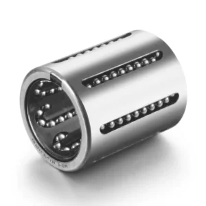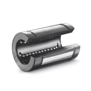
UCFS300 Series 4-Bolt Flange Bearing Units — Heavy Duty, Piloted Housing, Setscrew Locking
The UCFS300 series adds a precision pilot — a raised circular register on the back face of the flange housing — to the heavy-duty UCF300 configuration. This pilot locates the bearing housing concentrically in a matching bore in the machine frame or end plate, constraining the housing's radial position independently of the bolt-tightening sequence. The result is a bearing that can be removed and reinstalled multiple times without requiring re-centring relative to the shaft, making the UCFS300 the preferred choice for heavy-duty bearings that are replaced frequently, or for precision machine frames where bearing-to-bore concentricity is a design requirement.
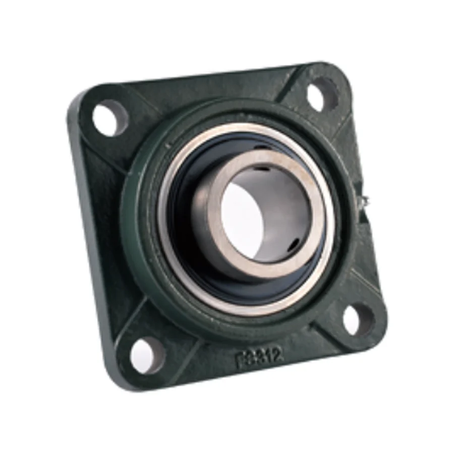
Pilot Locating Feature — Why It Matters for Heavy Duty Applications
In a standard UCF300 installation, the housing is located by the four mounting bolts alone. When the bolts are fully tightened, the housing is pulled against the mounting face and its radial position is determined by the clearance between the bolt shank and the bolt holes. On heavy-duty installations where the radial clearance of four M20–M36 bolts in their holes may translate to a few tenths of a millimetre of housing offset, this can be significant. The UCFS300 pilot eliminates this ambiguity: the pilot diameter fits into a precision-bored recess in the machine frame to an h7/H7 or similar transition fit, locating the housing concentrically before the bolts are tightened.
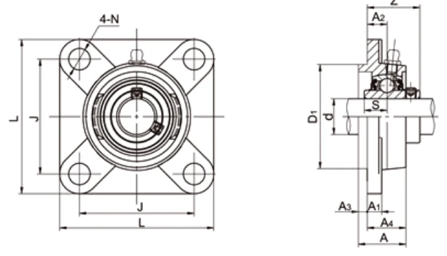
The D1 dimension in the specification table is the pilot diameter. The H and H1 dimensions are the pilot projection height and its internal relief depth, needed for the mating bore design. UK style is also available on request.
Key Features
☉
Precision Pilot on Back Face
Raised circular register locates housing concentrically in mating frame bore independently of bolt clearance. Enables repeatable reinstallation without re-centring.
⚙
Heavy-Duty UCF300-Class Housing
Same heavy cast iron flange plate and UC300 series insert bearing as UCF300. Full heavy-duty load capacity maintained with the pilot feature added.
🔧
Setscrew Locking
Dual 120° setscrew retention. Same bore suffix system and insert procedure as UCF300.
📏
Metric and Inch Bore
25–140 mm metric bore with inch bore variants available for smaller sizes (305–320). UCFS322–328 metric bore only.
▭
Hollow Base / Solid Base Available
Hollow base standard. Solid base (SB) on request.
✅
UK Style Available on Request
UK style flange with different outer dimension conventions available as special order.
Full Dimensional Specifications
| Unit No. | d mm | d inch | L mm | J mm | A2 mm | A1 mm | A mm | H mm | H1 mm | N mm | D1 mm | S mm | Z mm | Bolt | kg |
|---|---|---|---|---|---|---|---|---|---|---|---|---|---|---|---|
| UCFS305 / 305-14~16 | 25 | 7/8~1 | 110 | 80 | 9 | 22 | 29 | 7 | 13 | 16 | 80 | 15 | 32 | M14 | 1.3 |
| UCFS306 / 306-18/19 | 30 | 1-1/8~1-3/16 | 125 | 95 | 10 | 24 | 32 | 8 | 15 | 16 | 90 | 17 | 36 | M14 | 1.9 |
| UCFS307 / 307-20~22 | 35 | 1-1/4~1-3/8 | 135 | 100 | 11 | 27 | 36 | 9 | 16 | 19 | 100 | 19 | 40 | M16 | 2.4 |
| UCFS308 / 308-24/25 | 40 | 1-1/2~1-15/16 | 150 | 112 | 13 | 30 | 40 | 10 | 17 | 19 | 115 | 19 | 46 | M16 | 3.3 |
| UCFS309 / 309-26~28 | 45 | 1-5/8~2-3/16 | 160 | 125 | 14 | 33 | 44 | 11 | 18 | 19 | 125 | 22 | 49 | M16 | 4.0 |
| UCFS310 / 310-30/31 | 50 | 1-7/8~1-15/16 | 175 | 132 | 16 | 36 | 48 | 12 | 19 | 23 | 140 | 22 | 55 | M20 | 5.3 |
| UCFS311 / 311-32~34 | 55 | 2~2-1/8 | 185 | 140 | 17 | 39 | 52 | 13 | 20 | 23 | 150 | 25 | 58 | M20 | 6.2 |
| UCFS312 / 312-36~39 | 60 | 2-1/4~2-7/16 | 195 | 150 | 19 | 42 | 56 | 14 | 22 | 23 | 160 | 26 | 64 | M20 | 7.2 |
| UCFS313 / 313-40 | 65 | 2-1/2 | 208 | 166 | 15 | 40 | 58 | 18 | 22 | 23 | 175 | 30 | 60 | M20 | 8.9 |
| UCFS314 / 314-44 | 70 | 2-3/4 | 226 | 178 | 18 | 43 | 61 | 18 | 25 | 25 | 185 | 31 | 65 | M22 | 11.0 |
| UCFS315 / 315-48 | 75 | 3 | 236 | 184 | 21 | 48 | 66 | 18 | 25 | 25 | 200 | 32 | 71 | M22 | 13.0 |
| UCFS316 | 80 | — | 250 | 196 | 18 | 48 | 68 | 20 | 27 | 31 | 210 | 34 | 70 | M27 | 15.0 |
| UCFS317 / 317-52 | 85 | 3-1/4 | 260 | 204 | 24 | 54 | 74 | 20 | 27 | 31 | 220 | 40 | 80 | M27 | 17.0 |
| UCFS318 / 318-56 | 90 | 3-1/2 | 280 | 216 | 24 | 56 | 76 | 20 | 30 | 35 | 240 | 40 | 80 | M30 | 21.0 |
| UCFS319 / 319-60 | 95 | 3-3/4 | 290 | 228 | 39 | 74 | 94 | 20 | 30 | 35 | 250 | 41 | 101 | M30 | 25.0 |
| UCFS320 / 320-64 | 100 | 4 | 310 | 242 | 39 | 74 | 94 | 20 | 32 | 38 | 260 | 42 | 105 | M33 | 30.0 |
| UCFS322 | 110 | — | 340 | 266 | 35 | 71 | 96 | 25 | 35 | 41 | 300 | 46 | 106 | M36 | 39.0 |
| UCFS324 | 120 | — | 370 | 290 | 35 | 80 | 110 | 30 | 40 | 41 | 330 | 51 | 110 | M36 | 54.0 |
| UCFS326 | 130 | — | 410 | 320 | 35 | 85 | 115 | 30 | 45 | 41 | 360 | 54 | 116 | M36 | 71.0 |
| UCFS328 | 140 | — | 450 | 350 | 45 | 95 | 125 | 30 | 55 | 41 | 400 | 59 | 131 | M36 | 100.0 |
→ Scroll horizontally to view all columns. Catalogue dimensions for reference only — engineering drawings required before order.
D1 = pilot diameter. H = pilot projection height. H1 = pilot internal relief depth. Machine frame pilot bore: D1 with H7 fit recommended. UK style available on request. Solid base: suffix SB.
Applications
☉
Precision Machine End-Plate Supports
Drive shaft supports on precision machine tool end plates and gearbox housings where bearing-to-bore concentricity is a geometric tolerance requirement and repeated removal for maintenance must not affect shaft alignment.
⛏
Mining Conveyor Precision Frame Supports
Head pulley shaft supports on conveyor frames where the pilot locates the housing repeatably in the frame bore, eliminating the shaft re-alignment procedure that would otherwise follow each bearing replacement.
⚙
Large Fan & Blower Casing Mounts
Large centrifugal fan shaft supports on precision-bored fan casings where the pilot ensures the bearing centreline is concentric with the fan casing bore after each maintenance bearing replacement.
🏛
Cement & Process Plant Precision Supports
Process machinery bearing positions where a precision pilot bore is already machined into the frame and the UCFS300 pilot provides a direct fit without additional machining or alignment shims.
🔄
OEM Machine Builds Requiring Piloted Flange
Original equipment manufacturer builds where the machine frame drawing specifies a piloted flange bearing to ensure assembly-line repeatability of bearing position across multiple units.
▶
Repeat-Replacement High-Cycle Bearings
Any position where bearings are replaced frequently enough that eliminating the re-alignment step at each replacement produces measurable maintenance time savings.
📦 MOQ & Order Information
- Standard parts: quantity-based MOQ applies per model number.
- High-value / large items: minimum order by USD order value.
- New-client samples: 1–5 pcs available at sample price for first-time buyers.
- Multi-model combines: aggregate orders of USD 1,500 or more across models accepted.
- Special materials / processes: subject to process MOQ — confirm at inquiry stage.
- Retail (1–2 pcs): not accepted. Minimum sample order is 1–5 pcs at sample pricing.
Engineering drawings must be submitted and approved before order confirmation. Catalogue dimensions are for reference only.
Frequently Asked Questions
Difference between UCF300 and UCFS300?
UCFS300 adds a precision pilot register on the back face for concentric location in a matching frame bore. UCF300 is located by mounting bolts only.
What is D1?
D1 = pilot diameter. Machine frame needs a precision H7-fit bore of this diameter to accept the pilot.
Does UCFS300 have inch bore variants?
Yes for UCFS305–320. UCFS322–328 metric bore only.
What is the MOQ?
Standard parts: quantity-based MOQ. Samples 1–5 pcs. Multi-model from USD 1,500. Retail 1–2 pcs not accepted.
Request a Quote for UCFS300 Series
Provide shaft diameter, bore type, pilot diameter D1 requirement, and frame bore fit tolerance. Engineering drawings required before order. Contact us.