
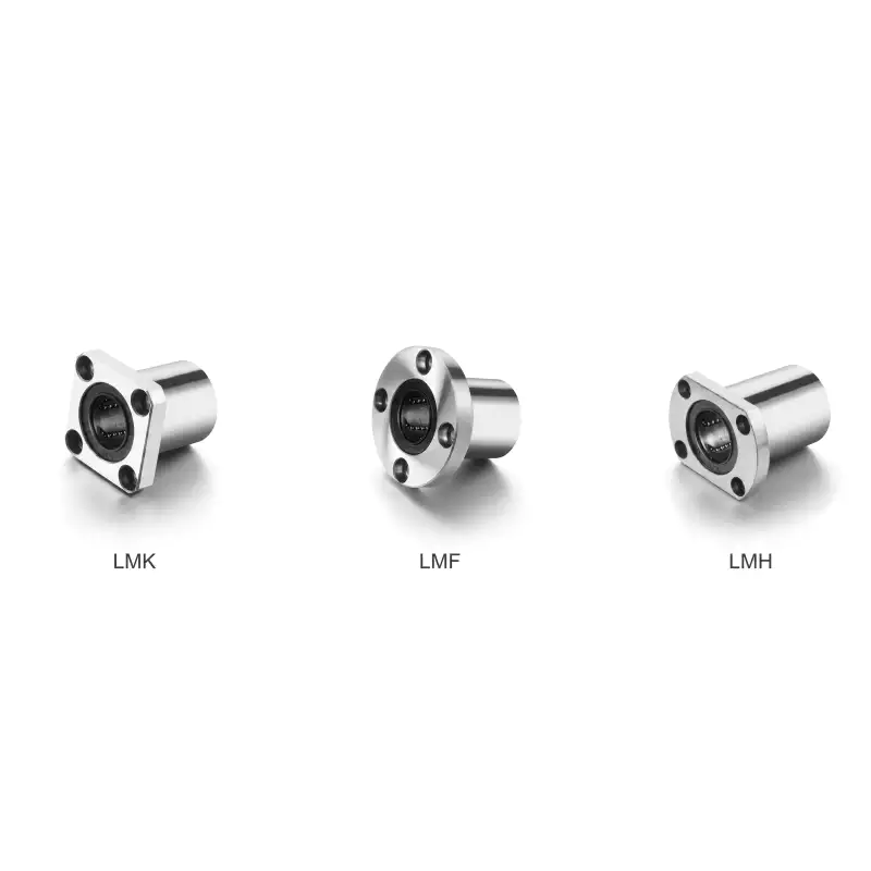
LMF LMK LMH Linear Bearing UU Series — Standard Flanged Sealed Ball Bushing
LMF/LMK/LMH…UU flanged recirculating linear ball bearing series — ISO Standard Flanged (JIS B 1192). 13 bore sizes. Dynamic load 206–4700 N. GCr15 HRC 58–64, dual lip seals, flanged housing mount.
MOQ: 50 pcs. Minimum order value USD 1,500; mixed orders and trial quantities welcome.
Linear Bearings › Flanged Series › ISO Standard Flanged (JIS B 1192)
LMF LMK LMH Linear Bearing UU Series — Standard Flanged Sealed Ball Bushing
13 bore sizes • Dynamic load 206–4700 N • ISO Standard Flanged (JIS B 1192)
GCr15 HRC 58–64
Flanged Mount
Dual Lip Seal
🆕 Series Overview
The LMF/LMK/LMH...UU series comprises three flange configurations — round (LMF), diamond (LMK), and square (LMH) — each sharing identical bore, outer diameter, and body length with the standard LM...UU cylindrical bearing. The flanged design adds a precision-ground face that registers directly against the housing shoulder, providing positive axial location without snap rings, end caps, or adhesive. All configurations conform to ISO/JIS B 1192 dimensional standards.
Round-flange (LMF) variants offer the most uniform bolt-load distribution and are preferred where maximum moment resistance is required. Diamond-flange (LMK) variants reduce the radial envelope of the bolt pattern, allowing closer bearing spacing. Square-flange (LMH) variants provide four bolt points at 90° intervals and resist bearing rotation under torsional loads.
⚙ Key Design Features
Flanged Axial Location
The precision-ground flange face registers directly against the housing shoulder, providing positive axial location without snap rings or adhesive retention.
GCr15 Chrome Steel
Through-hardened to HRC 58–64. Ball tracks ground to Ra 0.2 µm for full-film lubrication at the ball-race contact under rated load conditions.
Dynamic Load 206–4700 N
Covering 13 bore sizes for applications from lightweight instrument stages to heavy industrial press guides.
NBR Dual Lip Seals
Retain factory-applied NLGI-2 grease while excluding dust and contamination. Rated −20°C to +80°C continuous service.
PA66-GF30 Retainer
Glass-filled nylon cage maintains precise ball spacing across the full 360° circuit, preventing ball-to-ball contact and associated noise.
ISO/DIN Interchangeable
All dimensions conform to ISO Standard Flanged (JIS B 1192) standards for direct replacement compatibility with equivalent housings.
📋 Complete Specification Table
ⓘ Dynamic load rating C based on 50 km nominal life (L10). For 100 km design life, divide C by 1.26. Shaft h6/h7. Housing H7. All dimensions in mm, load ratings in N, weight in g.
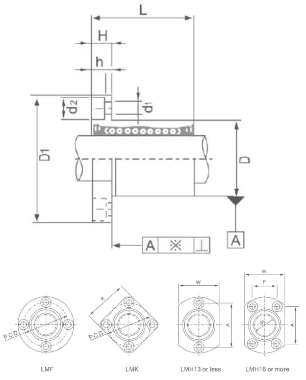
| LMF Model | LMK Model | LMH Model | Bore dr | OD D | Length L | H mm | PCD mm | Ball Cir. | Dyn C (N) | Sta Co (N) | Wt (g) |
|---|---|---|---|---|---|---|---|---|---|---|---|
| LMF6UU | LMK6UU | LMH6UU | 6 | 12 | 19 | 22 | 20 | 4 | 206 | 265 | 24 |
| LMF8UU | LMK8UU | LMH8UU | 8 | 15 | 24 | 28 | 24 | 4 | 274 | 392 | 37 |
| LMF10UU | LMK10UU | LMH10UU | 10 | 19 | 29 | 32 | 29 | 4 | 372 | 549 | 72 |
| LMF12UU | LMK12UU | LMH12UU | 12 | 21 | 30 | 32 | 32 | 4 | 510 | 784 | 76 |
| LMF13UU | LMK13UU | LMH13UU | 13 | 23 | 32 | 33 | 33 | 4 | 510 | 784 | 88 |
| LMF16UU | LMK16UU | LMH16UU | 16 | 28 | 37 | 37 | 38 | 5 | 774 | 1180 | 120 |
| LMF20UU | LMK20UU | LMH20UU | 20 | 32 | 42 | 42 | 42 | 5 | 882 | 1370 | 180 |
| LMF25UU | LMK25UU | LMH25UU | 25 | 40 | 59 | 59 | 51 | 6 | 980 | 1570 | 340 |
| LMF30UU | LMK30UU | LMH30UU | 30 | 45 | 64 | 64 | 60 | 6 | 1570 | 2740 | 470 |
| LMF35UU | LMK35UU | LMH35UU | 35 | 52 | 70 | 70 | 67 | 6 | 1670 | 3140 | 650 |
| LMF40UU | LMK40UU | — | 40 | 60 | 80 | 80 | 75 | 6 | 2160 | 4020 | 1060 |
| LMF50UU | LMK50UU | — | 50 | 80 | 100 | 100 | 92 | 6 | 3820 | 7940 | 2200 |
| LMF60UU | LMK60UU | — | 60 | 90 | 110 | 110 | 106 | 6 | 4700 | 10000 | 3000 |
🔭 Materials & Construction
All LMF/LMK/LMH bearings use GCr15 chrome-bearing steel (AISI 52100 / DIN 100Cr6), through-hardened to HRC 58–64 and precision-ground on all functional surfaces. Ball tracks are finish-ground to Ra 0.2 µm. The flange face is ground perpendicular to the bore axis to a runout tolerance of 0.02 mm for bore sizes up to 30 mm.
The ball retainer is injection-moulded from glass-fibre-reinforced nylon (PA66-GF30), maintaining precise ball spacing around the full 360° circuit to prevent ball-to-ball contact noise at higher traverse speeds. Dual NBR lip seals on both end faces retain factory-applied NLGI-2 lithium-complex grease while excluding dust, swarf, and splash contamination. Operating temperature range is −20°C to +80°C with standard seals and grease.
🏭 Typical Applications
CNC Machining Centres
Flanged linear bearings provide a positive axial stop against the housing shoulder, eliminating the need for snap rings in high-speed spindle carriage and tool-change axis applications where axial retention under reversal loads is critical.
Packaging & Labelling Machinery
High-cycle pick-and-place heads and label applicators use flanged linear bearings to achieve rapid, repeatable shaft insertion from one direction — the flange face acts as a hard stop that sets the bearing depth without measurement tools.
🔧 Installation & Maintenance
🔎 Flange Face Seating
Ensure the housing counterbore depth matches the bearing flange thickness. An under-depth counterbore leaves the flange proud of the housing face, creating a gap at the bolt interface that allows the bearing to rock under load and introduces harmonic error motion.
🔧 Bolt Torque Sequence
Tighten flange mounting bolts in a cross pattern to 30–50% of final torque, then complete to specification. Sequential tightening distorts the flange and shifts the bore axis by up to 0.05 mm, degrading shaft alignment.
📈 Shaft Specification
Use a hardened shaft (HRC 60+) ground to h6 or h7 tolerance with surface roughness Ra 0.4 µm or better. An undersized or soft shaft accelerates ball-track wear and reduces rated service life significantly.
⚙ Housing Bore Tolerance
Machine the housing bore to H7 tolerance. For square-flange (LMH/LMHP) variants, also verify the flange seating face is square to the bore within 0.02 mm to prevent cocking the bearing on assembly.
🔎 Selection Guide
First confirm the housing flange style and PCD from the specification table. Verify that outer diameter D and body length L match the housing bore and counterbore depth. If moment loads are present, calculate the equivalent bearing load using ISO 10285 before comparing with the dynamic load rating C.
①
Confirm Bore & Standard
Match bore diameter to shaft. Confirm ISO Standard Flanged (JIS B 1192) housing dimensions — mixing ISO and DIN outer diameters requires housing re-machining.
②
Select Flange Style
Round flange for maximum moment resistance; diamond flange for compact bolt clearance; square flange for torsional resistance.
③
Calculate Load & Life
Compute radial load P. Target L10 = (C/P)³ × 50 km. If life is marginal, specify the LUU extended variant to raise C without changing bore.
④
Contact Us
MOQ 100 units per model. Contact our team with engineering drawings confirming shaft diameter, housing bore depth, bolt PCD, load case, and target life.
❓ Frequently Asked Questions
📞 Ready to Order?
MOQ is 100 units per model. Provide engineering drawings with shaft diameter, housing bore depth, flange PCD, load case, stroke, speed, and target life. All catalogue data is for reference only — verify critical dimensions against current revision drawings before committing to tooling.
LMF/LMK/LMH…UU flanged recirculating linear ball bearing series — ISO Standard Flanged (JIS B 1192). 13 bore sizes. Dynamic load 206–4700 N. GCr15 HRC 58–64, dual lip seals, flanged housing mount.
MOQ: 50 pcs. Minimum order value USD 1,500; mixed orders and trial quantities welcome.
Related products
-
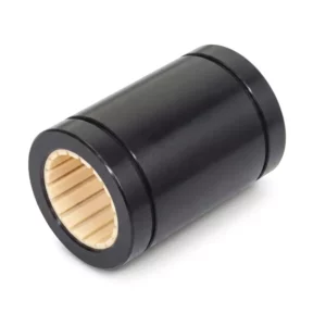
LIN-01R Series — Standard Cylindrical Plastic Linear Bearing with Aluminum Housing
-
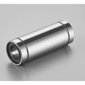
LME Linear Bearing LUU Series — Euro Extended Length Ball Bushing
-
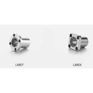
LMEF LMEK Linear Bearing UU Series — Euro Standard Flanged Sealed Ball Bushing
-
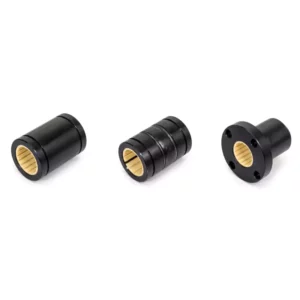
LIN-01 Series Sliding Membrane — Standard Split Type Plastic Linear Bearing
-
LIN-01K Series Sliding Membrane — Split Type with Keyway Plastic Linear Bearing
-
LMEFC LMEKC Linear Bearing UU Series — Euro Flanged Sealed Ball Bushing with Locking Screw