K / U Silver Series Bearing Inserts
Compare mounting style, shaft locking, bore range and installation envelope before selecting the alternative.

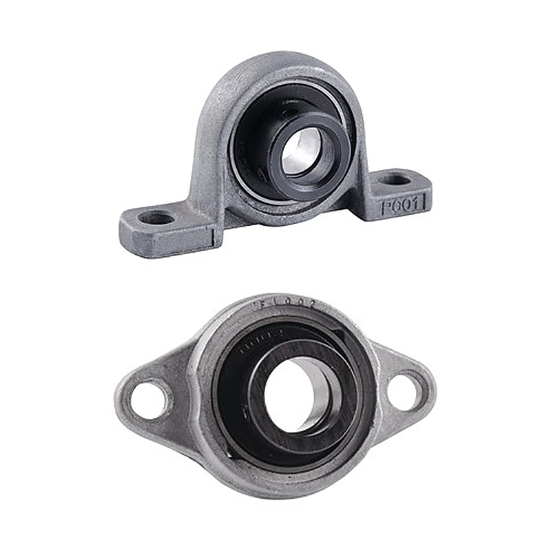
On UP-UFL-SERIES, the mechanical form is light-duty pillow block and 2-bolt flange units, the construction is zinc-alloy / light-duty housed construction, and the shaft connection is eccentric locking collar. The machine-side comparison should cover two-hole spacing, flange length and shaft centre position.
Start by reserving a clear shaft line and the envelope needed by the chosen mounting form. Leave realistic room for bolts, collars, grease access and eventual removal. A housing that fits in a CAD model can still become awkward on the shop floor if a guard blocks the fastener path or if a wrench cannot reach the locking feature after the rest of the machine is assembled.
MOQ: 50 pcs. Minimum order value USD 1,500; mixed orders and trial quantities welcome.
On UP-UFL-SERIES, the mechanical form is light-duty pillow block and 2-bolt flange units, the construction is zinc-alloy / light-duty housed construction, and the shaft connection is eccentric locking collar. The machine-side comparison should cover two-hole spacing, flange length and shaft centre position.
This product family is commonly reviewed for light-duty conveyors, compact auxiliary machinery and modest shaft-support positions. Actual load, speed, cleaning and contamination conditions should be stated for the ordered position.
New-machine projects allow the bearing position to be engineered before the frame, guards and nearby components become fixed. That makes early interface planning more valuable than simply selecting a familiar housing and drawing the structure around it later.
Start by reserving a clear shaft line and the envelope needed by the chosen mounting form. Leave realistic room for bolts, collars, grease access and eventual removal. A housing that fits in a CAD model can still become awkward on the shop floor if a guard blocks the fastener path or if a wrench cannot reach the locking feature after the rest of the machine is assembled.
The design record should identify the exact product reference, the shaft size, the locking method and the mounting dimensions that locate the unit. Put these items in the bill of materials rather than relying on a generic note such as “flange bearing.” Doing so makes the first build easier to inspect and gives future maintenance teams a better starting point when the same support must be replaced.
Think about spares at the same stage. If several positions could share one product, verify the interfaces deliberately instead of assuming commonality because the shaft diameters match. A small amount of design discipline now can prevent a plant from carrying several almost-identical housings that cannot actually substitute for one another.
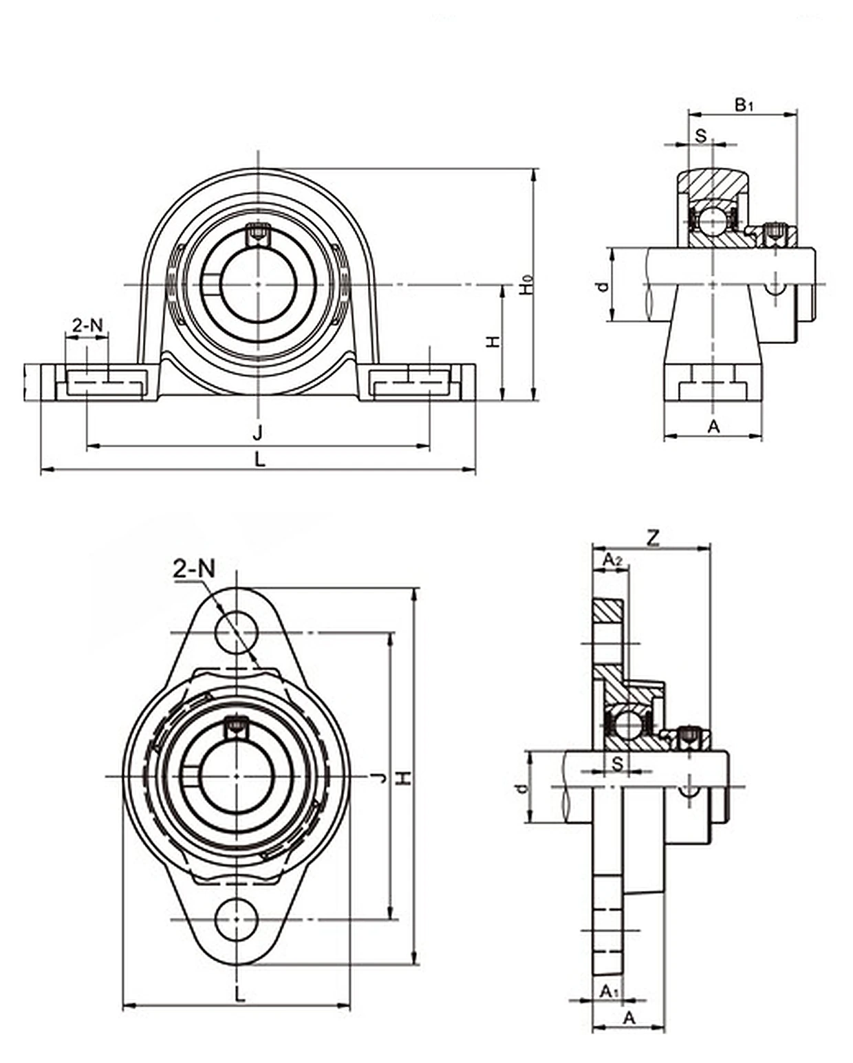
Use the drawing to compare two-hole spacing, flange length and shaft centre position. Read the printed values rather than scaling the illustration; for modified equipment, send current machine measurements with the enquiry.
| Representative bore | 25 mm |
|---|---|
| UP005 H | 32 mm |
| UP005 L | 112 mm |
| UP005 J | 90 mm |
| UFL005 H | 71 mm |
| UFL005 J | 55 mm |
| Bolt size | M8 |
UP005 / UFL005 can be considered for compact conveyors where its light-duty pillow block / 2-bolt flange geometry matches the machine. Base footprint and shaft-centre height are the first fit checks on existing frames.
For auxiliary machinery, the eccentric collar arrangement changes installation access and shaft retention. Confirm that detail before standardising the spare.
In packaging equipment service, use the construction of UP005 / UFL005 only where the actual moisture, contamination and cleaning conditions match the selected product family.
Compare mounting style, shaft locking, bore range and installation envelope before selecting the alternative.
Compare mounting style, shaft locking, bore range and installation envelope before selecting the alternative.
For UP-UFL-SERIES, provide the build quantity, shaft size, machine drawing and service environment.
On UP-UFL-SERIES, the mechanical form is light-duty pillow block and 2-bolt flange units, the construction is zinc-alloy / light-duty housed construction, and the shaft connection is eccentric locking collar. The machine-side comparison should cover two-hole spacing, flange length and shaft centre position.
Start by reserving a clear shaft line and the envelope needed by the chosen mounting form. Leave realistic room for bolts, collars, grease access and eventual removal. A housing that fits in a CAD model can still become awkward on the shop floor if a guard blocks the fastener path or if a wrench cannot reach the locking feature after the rest of the machine is assembled.
MOQ: 50 pcs. Minimum order value USD 1,500; mixed orders and trial quantities welcome.