
Grid Coupling Series
Each series is engineered for a specific installation configuration, connection interface, or integrated function. Select the series that matches your drivetrain geometry and maintenance requirements.
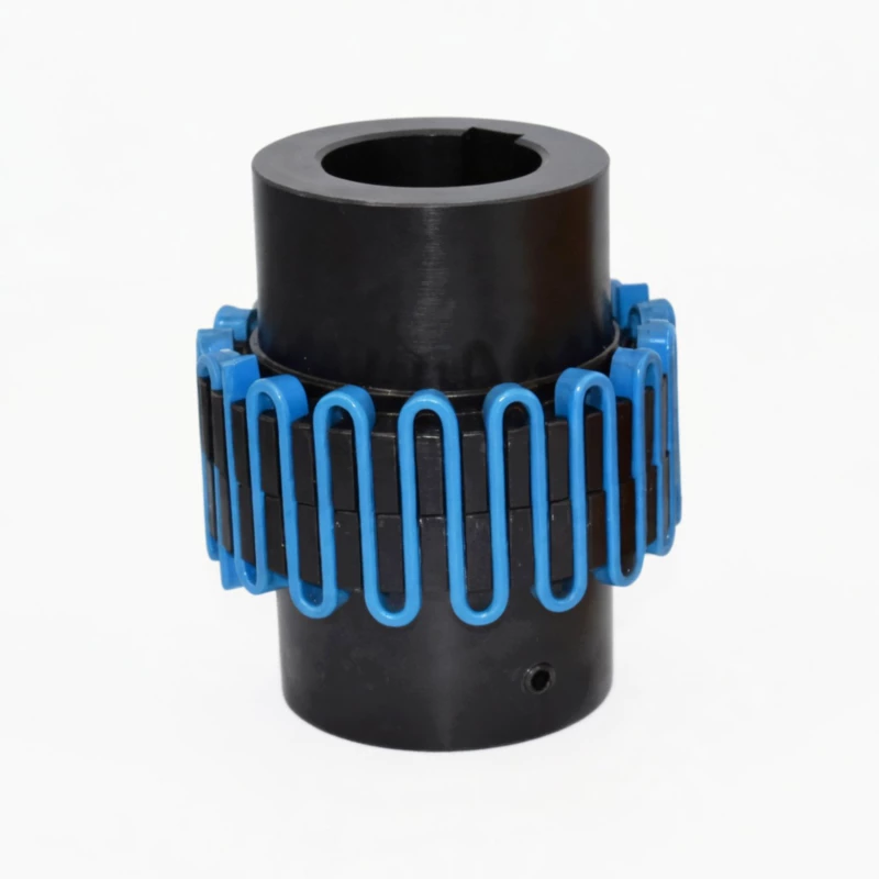
Shaft bore: 18 – 500 mm | 25 sizes
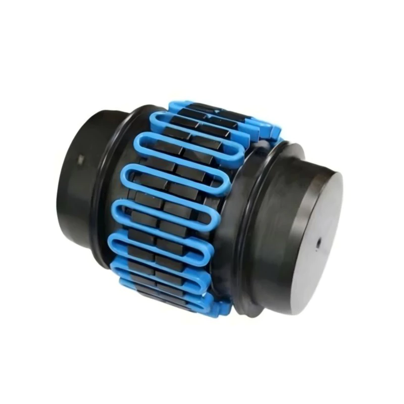
Axial shell removal | 25 sizes
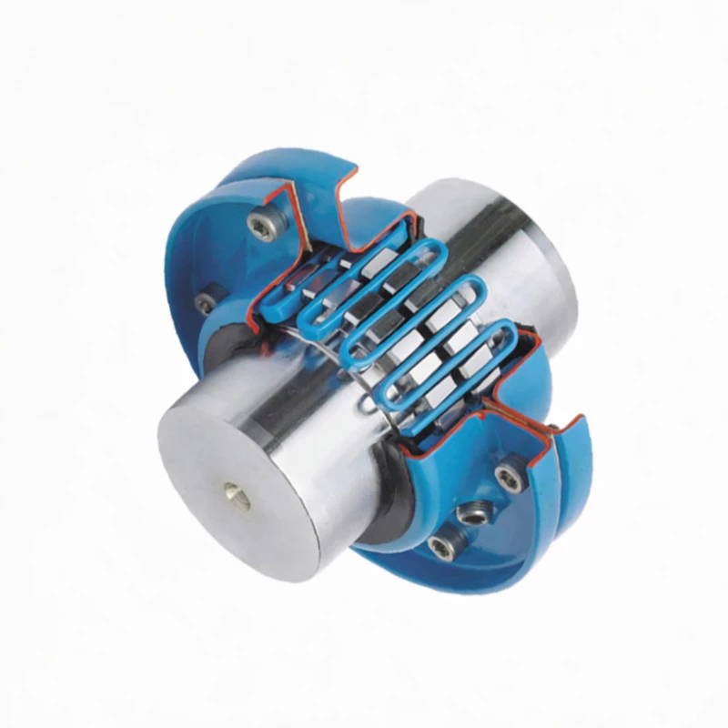
Shaft bore: 18 – 260 mm | 16 sizes
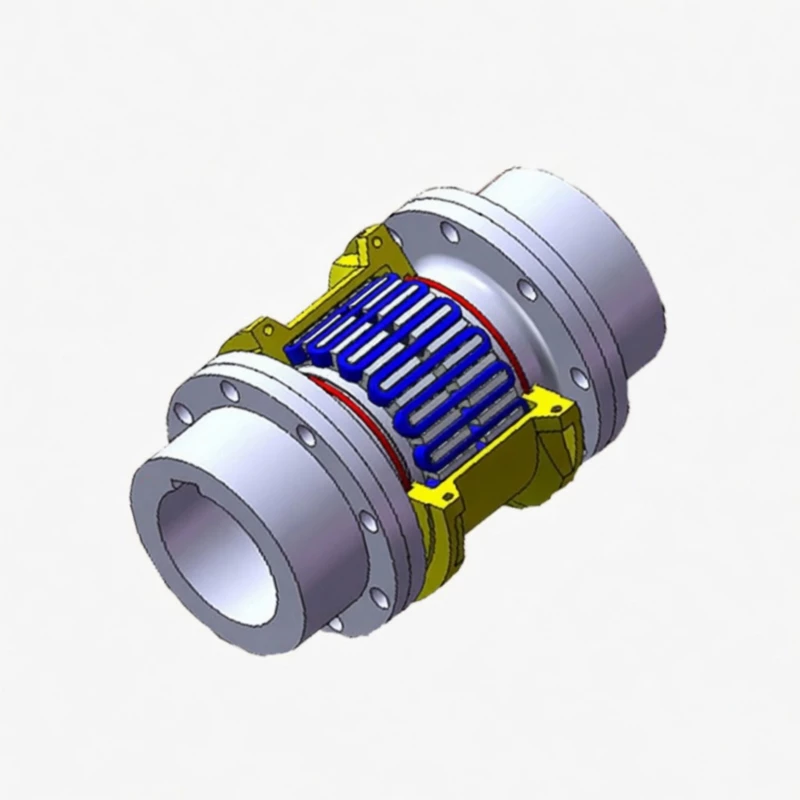
Adjustable L2 gap | 19 sizes
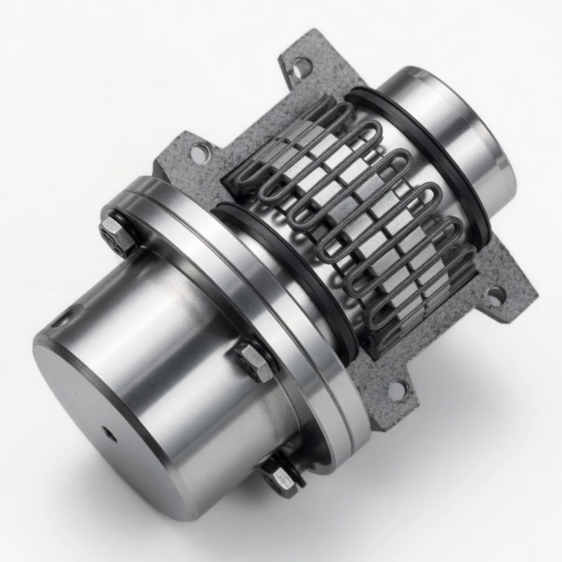
Hybrid flange-to-shaft | 19 sizes
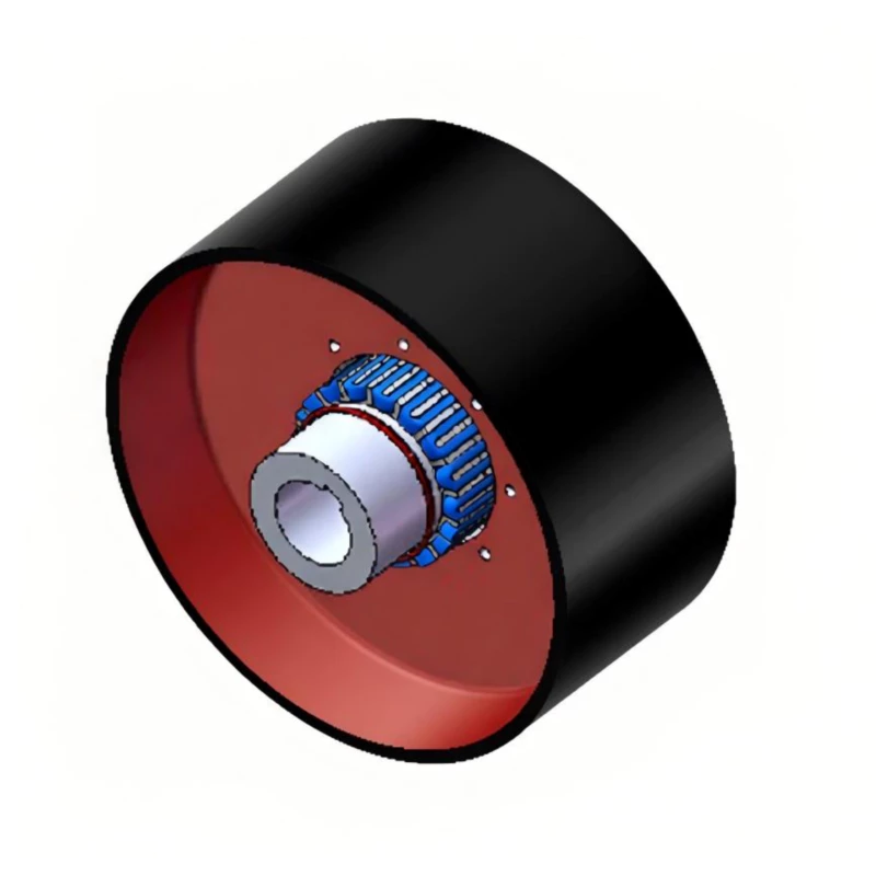
Integrated drum 160–710 mm | 8 sizes
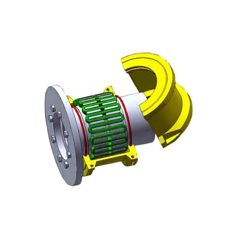
Disc diameter 315–900 mm | 11 sizes
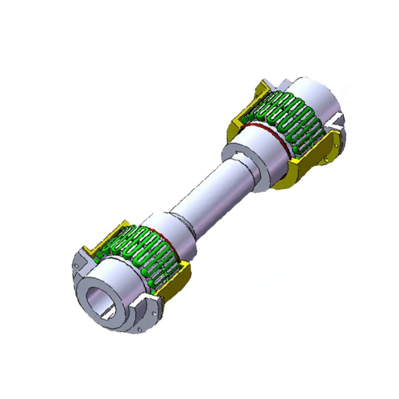
Dual spring assemblies | 16 sizes
What Is a Grid Coupling?
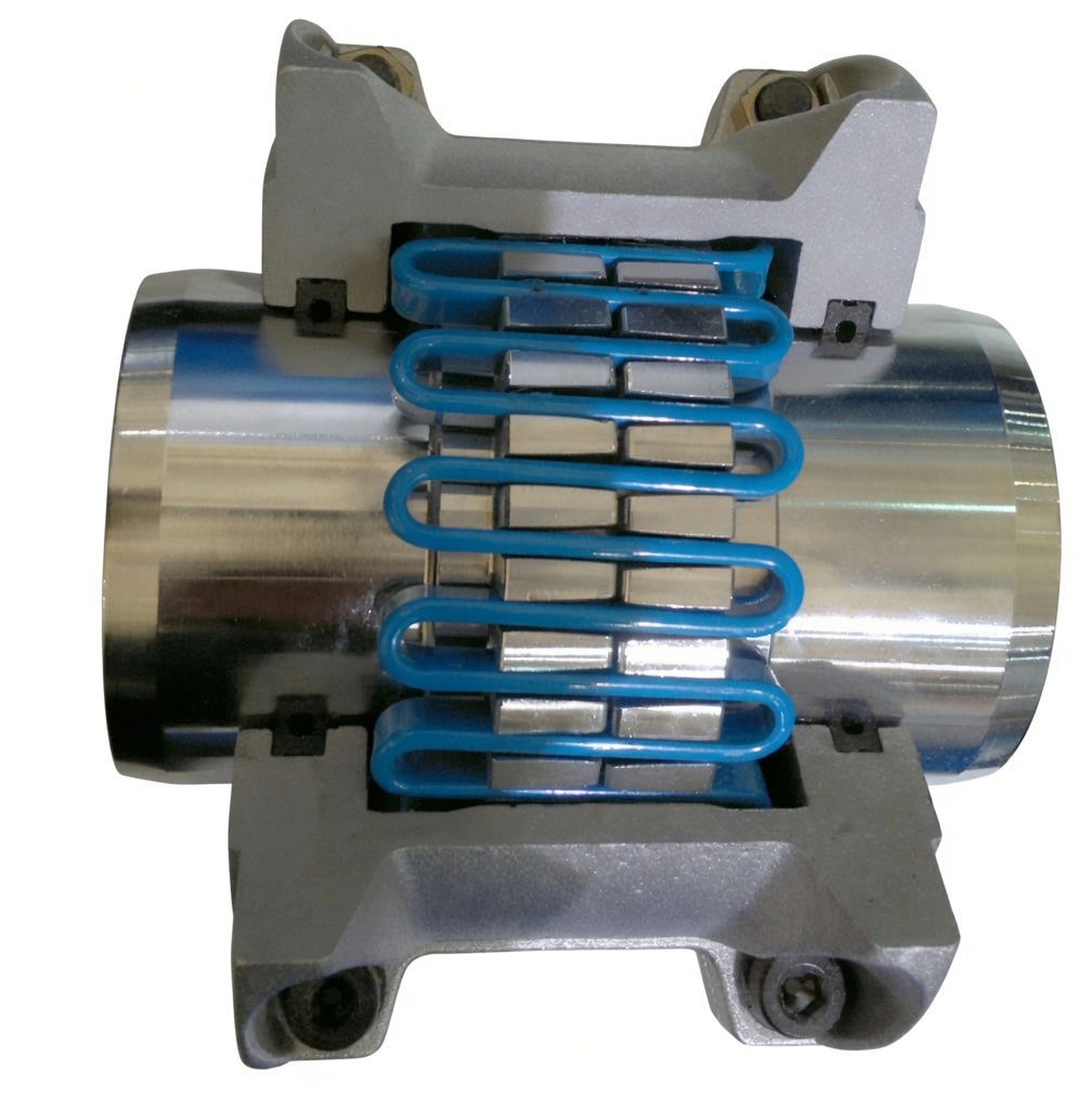
A grid coupling — also known as a serpentine spring coupling or snake spring coupling — is a metallic flexible coupling that transmits torque through a continuous wave-form spring element interleaved within the tooth grooves of two precision-machined hub halves. Unlike elastomeric couplings, the spring element is made from high-grade spring steel, giving grid couplings a unique combination of elasticity, high torque capacity, and exceptional fatigue resistance that non-metallic designs cannot match.
The serpentine spring engages the circumferential tooth faces of both hub halves simultaneously. Under torsional or angular misalignment, the spring undergoes controlled elastic deformation, absorbing shock loads, preventing torsional resonance, and protecting connected machinery from vibration-induced fatigue. The average vibration damping rate of 36% and transmission efficiency of 99.47% make grid couplings the preferred choice across mining, metallurgy, power generation, chemical processing, and heavy manufacturing.
GBC grid couplings cover a torque range from 45 N·m to 800,000 N·m across eight distinct series, accommodating shaft bore diameters from 18 mm to 500 mm. Every series shares the same serpentine spring technology, ensuring identical damping characteristics and a unified spare parts philosophy across your entire facility.
Why Choose a Grid Coupling?
How a Grid Coupling Works
The grid coupling transmits torque through the axial engagement of a continuous serpentine (snake-shaped) spring element within the alveolar tooth grooves machined into both hub halves. When the driving shaft rotates, the spring presses against the tooth flanks of both hubs simultaneously, transferring torque from the motor side to the driven equipment.
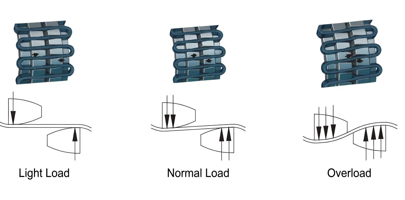
The spring's variable-stiffness characteristic is a key engineering advantage: stiffness increases progressively as deflection grows, providing soft response to small misalignments and firm resistance to large shock loads. This self-regulating behaviour is not achievable with fixed-stiffness rigid or disc couplings. For detailed selection guidance, visit the complete GBC coupling range.
Industry Applications
Grid couplings are proven across a broad range of heavy industries where torsional reliability, vibration control, and low maintenance cost are non-negotiable. The table below maps common drive configurations to the recommended grid coupling series.
| Industry | Typical Drive Application | Recommended Series | Key Requirement |
|---|---|---|---|
| Mining & Minerals | Ball mills, crushers, belt conveyors, skip hoists | JS, JSB, JSZ | Shock load absorption, dustproof |
| Steel & Metallurgy | Rolling mill drives, continuous casters, crane hoists | JS, JSD, JSZ | Torsional reversal, high torque |
| Power Generation | Turbine-generator sets, boiler feed pumps, induced-draft fans | JSD, JSS, JSJ | Torsional damping, flange interface |
| Chemical & Petrochemical | Centrifugal compressors, reactor agitators, process pumps | JSS, JSD, JSB | Vibration isolation, chemical resistance |
| Marine & Offshore | Propulsion gearboxes, pump packages, winch drives | JSS, JSD | Compact axial envelope, high reliability |
| Cement & Building Materials | Rotary kilns, vertical mills, clinker cooler drives | JS, JSB | Sustained heavy load, infrequent maintenance |
| Cranes & Hoists | Overhead crane hoists, gantry travel drives, winches | JSZ, JSP | Integrated braking, fail-safe holding |
| Paper & Pulp | Press section drives, winders, calendar roll drives | JSP, JS | Precision torque control, low vibration |
| Pipeline Pumping | Booster pump sets across structural gaps | JSJ | Long-span intermediate shaft |
| Food & Beverage | Mixers, centrifugal separators, conveyors | JSB | Compact profile, easy maintenance |
Not sure which series fits your application? Use our engineering enquiry form to submit your torque, speed, bore, and installation dimensions. Our technical team will recommend the optimal series and model within one business day.
Series Selection Guide
Choosing the right grid coupling series depends on four primary factors: the required installation configuration, the torque and speed range, the shaft interface type, and any integrated braking requirements. Use the decision tree below to identify your series.
Torque Calculation: Calculate design torque using Tc = K x 9,550 x Pw / n, where Pw is drive power in kW, n is operating speed in rpm, and K is the service factor for your prime mover and driven machine class. The chosen coupling Tn must satisfy Tn ≥ Tc. For service factor tables and bore selection charts, request our full selection guide.
Frequently Asked Questions
What is the difference between a grid coupling and a gear coupling?
How frequently does a grid coupling spring need to be replaced?
Can grid coupling springs be used across different series of the same torque class?
What lubricant should be used in a grid coupling?
Can grid couplings be installed on vertical shafts?
What misalignment tolerances do GBC grid couplings accommodate?
Are custom bore diameters and keyway specifications available?
Grid Coupling Technical Overview
Material and Construction
The serpentine spring is manufactured from premium spring steel (typically 65Mn or 60Si2Mn alloy) with closely controlled heat treatment cycles to achieve the optimal combination of tensile strength, fatigue life, and elastic modulus. Hub halves are precision-machined from carbon steel forgings, with tooth profiles cut to tight tolerances to ensure uniform spring contact across the full tooth width.
Shell housings are aluminium alloy for smaller and medium sizes (up to JS22 / JSB12 equivalents) to reduce rotating mass and centrifugal loading, transitioning to steel fabrications for the largest sizes where structural rigidity demands outweigh weight considerations.
Installation and Alignment
Grid couplings are installed by mounting each hub half on its respective shaft with the appropriate keyway fit, setting the shaft gap to the specified C clearance dimension, inserting the serpentine spring, and fitting the shell halves. Alignment should be checked using dial indicators or laser alignment systems before the shell is closed and filled with grease.
Maximum permissible misalignment values (radial, angular, and axial) are published for each model size. These values represent installation tolerances — the coupling compensates for additional dynamic misalignment arising from thermal growth and foundation movement during operation.
Standards and Certifications
GBC grid couplings are manufactured in accordance with Chinese mechanical industry standards JB/T 8869-2000 (JS, JSB, JSS, JSD, JSZ, JSP, JSJ series) and JB/T 8896-2000 (JS horizontal mount series). Products are produced under a quality management system certified to ISO 9001, with dimensional inspection records available for all custom bore orders.
Spare Parts and Interchangeability
The serpentine spring element is the primary maintenance item in a grid coupling. Springs are interchangeable across all series variants (JS, JSB, JSS, JSD, JSJ, JSZ, JSP) of the same nominal torque class, allowing facilities to maintain a single spring inventory per torque rating regardless of the coupling configuration installed. Hub halves and shells are series-specific but are stocked across all sizes.
For scheduled maintenance programmes, GBC recommends holding one spare spring per coupling installed on critical drives, with inspection intervals of 6 to 12 months and lubrication intervals of 2,000 to 4,000 operating hours. Explore the full GBC coupling catalogue for technical documentation and dimensional drawings for each series.
Find the Right Grid Coupling for Your Drive
Submit your torque, speed, shaft bore, and installation configuration to our engineering team. We will identify the optimal series and model, provide a detailed quotation, and arrange delivery to your site worldwide.
Request Engineering Support Browse All Couplings