UCPE200 Series Pillow Block Bearing Units — Solid Base Housing, Setscrew Locking
Most pillow block applications are well served by the hollow-base UCP200 housing. But certain industries have learned from field experience that the hollow base creates a problem: it acts as a trap for abrasive material. In timber processing, wood chips and sawdust pack into the hollow base cavity, retaining moisture and accelerating corrosion at the mounting interface. In mineral screening, fine dust in the hollow section consolidates into a hard plug that can crack the housing flange if not cleared before removal. The UCPE200 eliminates this failure mode entirely by providing an integral solid base.
Solid Base Design — Structural and Maintenance Advantages
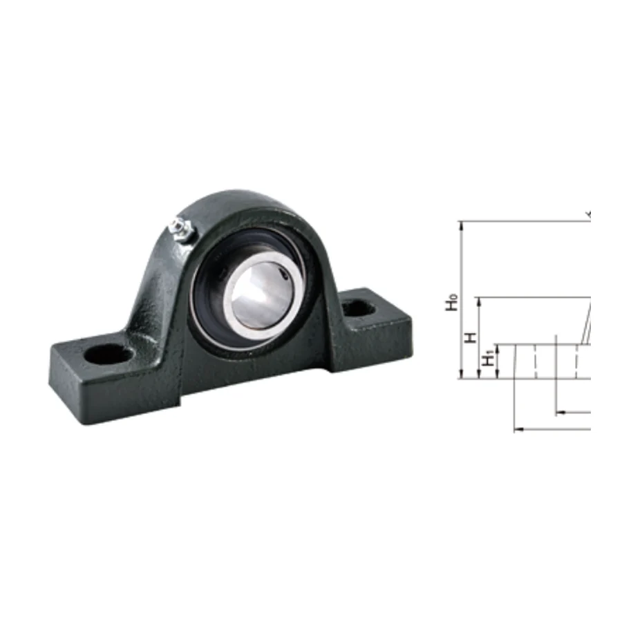
The UCPE200 solid base is cast integral with the housing rather than bolted on. This one-piece construction eliminates the joint line at the base that can become a contamination entry point in hollow-base designs, and it provides a continuous flat mounting surface across the full housing width. The additional material in the base also contributes to the housing moment of inertia at the mounting plane, increasing resistance to housing rotation under lateral loads from belt drives or chain pulls.
Key Features
☰
Integral Solid Base
Cast as one piece with the housing. No hollow cavity to trap wood chips, dust, or moisture. Full-width flat mounting surface.
🔧
Dual Setscrew Locking
Two setscrews at 120° — same retention geometry as UCP200. Both metric and inch bolt hole options (A3 dimension).
↔
Wider Inner Ring Insert
Self-aligning UC insert bearing accommodates 2° shaft misalignment. Wide inner ring with setscrew seating surfaces and axial float capacity.
⚙
Industry-Proven Housing Profile
PE-style solid base housing geometry used in timber, mining, and screening machinery for decades.
💧
End Cap Compatible
Pressed steel end caps (SM closed, S open) available for additional contamination exclusion.
📏
Metric and Inch Bolt Patterns
A3 column specifies the inch-standard bolt hole dimension, allowing UCPE200 installation in frames drilled to inch-based drawings.
Full Dimensional Specifications
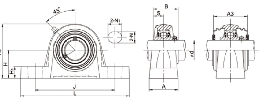
| Unit No. | d mm | d inch | H mm | L mm | J mm | A mm | N mm | N1 mm | H1 mm | H0 mm | B mm | S mm | A3 mm | Bolt mm | Bolt in | kg |
|---|---|---|---|---|---|---|---|---|---|---|---|---|---|---|---|---|
| UCPE201~203 / 201-8~203-11 | 12~17 | 1/2~11/16 | 30.2 | 124 | 95 | 31 | 11 | 15 | 14 | 57.1 | 26 | 10 | — | M8 | 5/16 | 0.57 |
| UCPE204 / 204-12 | 20 | 3/4 | 33.3 | 127 | 95 | 38 | 13 | 16 | 15 | 65 | 31 | 12.7 | 46.4 | M10 | 3/8 | 0.82 |
| UCPE205 / 205-14/15/16 | 25 | 7/8~1 | 36.5 | 140 | 105 | 38 | 13 | 16 | 16 | 70 | 34.1 | 14.3 | 48 | M10 | 3/8 | 0.94 |
| UCPE206 / 206-17/18/19/20 | 30 | 1-1/16~1-1/4 | 42.9 | 160 | 121 | 48 | 17 | 21 | 18 | 83 | 38.1 | 15.9 | 52 | M14 | 1/2 | 1.46 |
| UCPE207 / 207-20/21/22/23 | 35 | 1-1/4~1-7/16 | 47.6 | 167 | 127 | 48 | 17 | 21 | 19 | 94 | 42.9 | 17.5 | 59 | M14 | 1/2 | 1.76 |
| UCPE208 / 208-24/25 | 40 | 1-1/2~1-9/16 | 49.2 | 184 | 137 | 54 | 17 | 25 | 19 | 100 | 49.2 | 19.0 | 68.2 | M14 | 1/2 | 2.13 |
| UCPE209 / 209-26/27/28 | 45 | 1-5/8~1-3/4 | 54 | 190 | 146 | 54 | 17 | 25 | 20 | 108 | 49.2 | 19.0 | 70 | M14 | 1/2 | 2.43 |
| UCPE210 / 210-30/31/32 | 50 | 1-7/8~2 | 57.2 | 206 | 159 | 60 | 20 | 25 | 22 | 114 | 51.6 | 19.0 | 76 | M16 | 5/8 | 3.13 |
| UCPE211 / 211-32/34/35 | 55 | 2~2-3/16 | 63.5 | 219 | 171 | 60 | 20 | 25 | 22 | 126 | 55.6 | 22.2 | 76 | M16 | 5/8 | 3.87 |
| UCPE212 / 212-36/38/39 | 60 | 2-1/4~2-7/16 | 69.9 | 241 | 184 | 70 | 20 | 25 | 25 | 138 | 65.1 | 25.4 | 89 | M16 | 5/8 | 5.51 |
| UCPE213 / 213-40 | 65 | 2-1/2 | 76.2 | 265 | 203 | 70 | 25 | 29 | 27 | 150 | 65.1 | 25.4 | 89 | M20 | 3/4 | 6.63 |
| UCPE214 / 214-44 | 70 | 2-3/4 | 79.4 | 266 | 210 | 72 | 25 | 31 | 27 | 156 | 74.6 | 30.2 | 98 | M20 | 3/4 | 7.46 |
| UCPE215 / 215-47/48 | 75 | 2-15/16~3 | 82.6 | 275 | 217 | 74 | 25 | 31 | 28 | 163 | 77.8 | 33.3 | 97 | M20 | 3/4 | 8.21 |
→ Scroll table horizontally to view all columns. Catalogue dimensions for reference only — engineering drawings required before order.
A3 = inch-standard bolt hole dimension. End caps: SM (closed), S (open) — specify with order.
Applications
🌳
Sawmill & Timber Processing
Log feed roller shafts, edger drive shafts, and green chain conveyor drives where wood chips, bark, and sawdust accumulate continuously. Solid base eliminates the contamination trap.
⛏
Mineral Screening & Aggregate
Vibrating screen deck shafts and feeder trough drives in quarry and mining operations where fine mineral dust consolidated in a hollow base can crack the housing flange under vibration.
🏛
Building Materials Production
Brick and tile extrusion screw supports, clay mixing paddle shafts, and roof tile press roller bearings in high clay moisture and abrasive grit environments.
⚙
Panel Board & MDF Plants
Fibre mat transport conveyor drives and hot press infeed roller shafts where wood fibre adhesive residue accumulates around bearing housings.
🌿
Biomass & Pellet Processing
Pellet mill conditioning screw shafts and hammer mill drive bearings where organic material and steam condensate create highly corrosive conditions.
🔄
Inclined & Vertical Shaft Installations
Any application where mounting orientation is not horizontal and hollow-base foot compliance would create uneven bolt preload. Solid base provides consistent clamping regardless of shaft angle.
📦 MOQ & Order Information
- Standard parts: quantity-based MOQ applies per model number.
- High-value / large items: minimum order by USD order value.
- New-client samples: 1–5 pcs available at sample price for first-time buyers.
- Multi-model combines: aggregate orders of USD 1,500 or more across models accepted.
- Special materials / processes: subject to process MOQ — confirm at inquiry stage.
- Retail (1–2 pcs): not accepted. Minimum sample order is 1–5 pcs at sample pricing.
Detailed engineering drawings must be submitted and approved before order confirmation. Catalogue dimensions are for reference only.
Installation & Maintenance Notes
The solid base provides a flat, consistent mounting surface — ensure the machine frame face is clean, flat, and free of chips before bolting down. In sawmill applications, inspect and clean the housing exterior and seal lips after every shift to prevent wood chip accumulation from building a moisture bridge to the shaft. End caps (SM or S) are strongly recommended in dusty environments. For the equivalent hollow-base standard duty unit, see the UCP200 series.
Frequently Asked Questions
Why solid base in sawmill/wood processing?
Hollow base accumulates chips and moisture causing corrosion and housing damage at removal. Solid base eliminates the cavity entirely.
Is UCPE200 the same size as UCP200?
H, L, J match UCP200 for equivalent bore. A dimension may vary slightly. Unit weight is higher.
Are inch bolt holes available?
Yes — A3 column gives the inch-standard bolt hole dimension for both metric and inch machine frames.
What is the MOQ?
Standard parts: quantity-based MOQ. Samples 1–5 pcs. Multi-model from USD 1,500. Retail 1–2 pcs not accepted.
Request a Quote for UCPE200 Series
Specify shaft diameter, bore type (metric or inch), and end cap requirement (SM/S). Contact us.