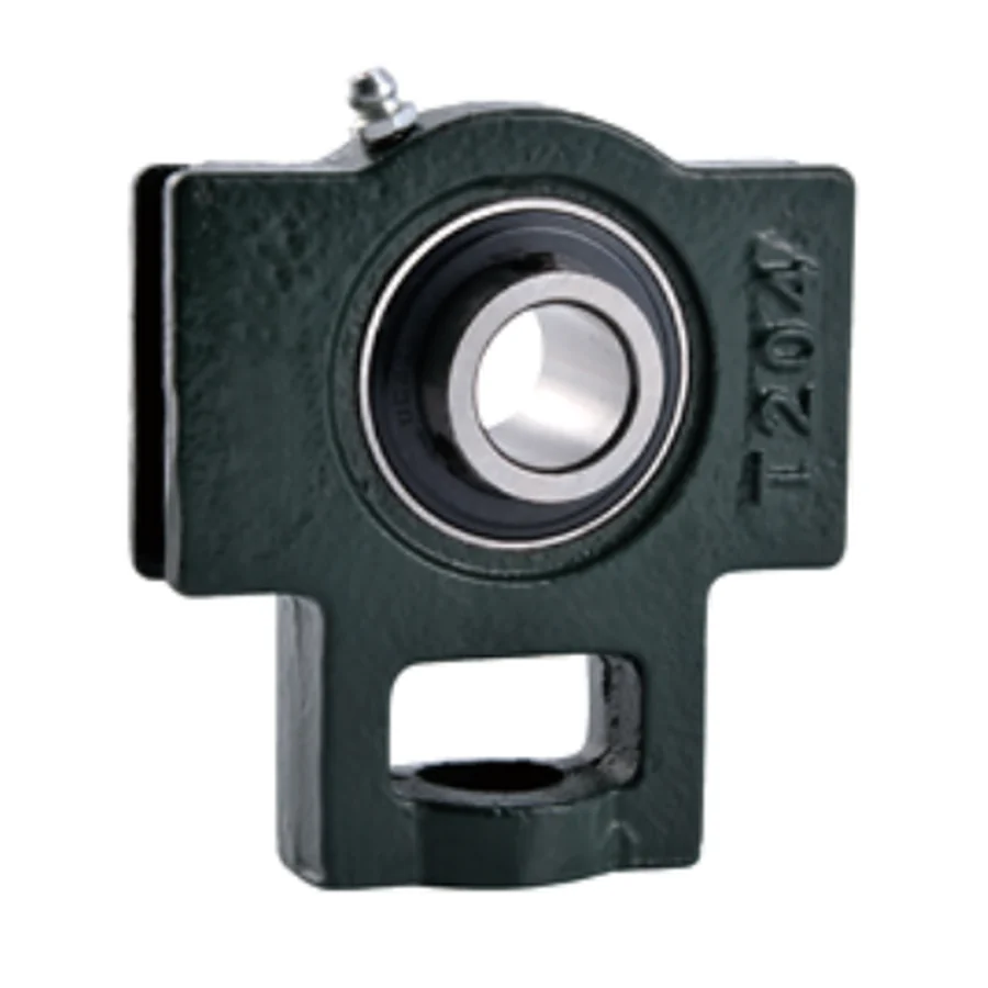
UCT200 Series Take Up Bearing Units — Standard Duty, Setscrew Locking
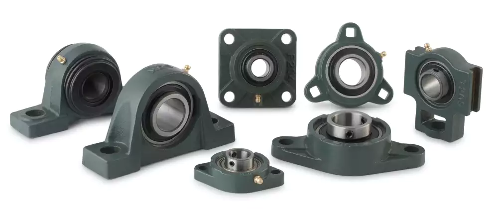
A take-up unit combines a mounted bearing with a slotted cast iron housing that slides along a frame rail or between guide faces, driven by an adjusting screw. The slot travel (controlled by dimensions N1 and N2 — slot width and slot length) allows the bearing centreline to be moved axially or laterally relative to the drive structure after installation, tensioning a belt, chain, or timing drive without removing the bearing from the shaft. Once the correct tension is set, the housing is locked in position by tightening the frame bolts through the slot. This combination of bearing and tensioning mechanism in a single unit reduces the number of components on a conveyor or drive frame, lowers installation time, and makes re-tensioning after belt stretch a tool-only operation without shaft removal.
The UCT200 is the take-up format equivalent of the UCP200 pillow block. The UC series wide inner ring insert and dual 120° setscrew are identical between the two housings — the difference is entirely in the outer housing: the UCT200 replaces the fixed pillow base with a slotted take-up frame that can be moved by the tensioning screw. This means the UCT200 insert bearing, maintenance procedure, and bore suffix system are fully consistent with the rest of the UC200 family (UCF200, UCFL200, UCFA200), giving maintenance teams a single insert type to stock across pillow block, flange, and take-up positions on the same machine.
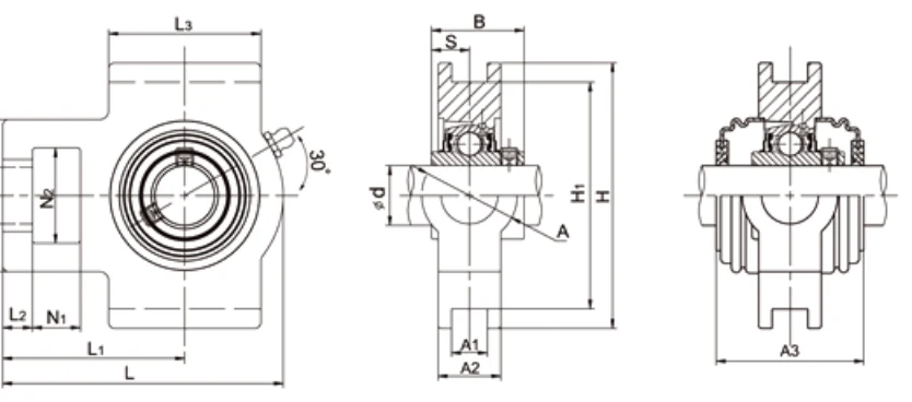
Take-Up Frame Dimensions — N1, N2, L, and the Tensioning Geometry
The UCT200 specification table introduces several dimensions not present in pillow block or flange unit tables. N1 is the slot width — the bolt shank passes through this slot and the housing slides along the slot as the tensioning screw is adjusted. N2 is the slot length — the total travel available before the housing reaches the end of the slot. L is the overall frame length including the slot. L1 is the bearing housing width across the take-up frame slots. L2 is the distance between the two slot centrelines. L3 is the housing body length. H1 is the centreline height, H2 is the total frame height, and A3 (where present) is the frame-end dimension at larger bore sizes.
Key Features
⇨
Slotted Take-Up Frame with N1×N2 Travel
N1 (slot width) and N2 (slot length) define the bolt passage and housing travel range. Adjust tensioning screw to move the bearing centreline; lock by tightening frame bolts through the slot.
🔧
Setscrew Locking — UC Insert
Dual 120° setscrew, wide inner ring UC insert. Same insert as UCP200 pillow block and UCF200/UCFL200 flange units — one insert type across all standard-duty UC housings.
📏
Metric and Inch Bore
12–90 mm metric bore with inch bore variants per housing size. UCWT201–203 compact variant for small bore positions.
☑
End Caps Available
SM (closed) or S (open) pressed steel end caps on request.
⚙
Direct Tensioning Without Shaft Removal
Re-tension belt or chain by turning the adjusting screw while the shaft runs. No need to remove the shaft or dismantle the drive for routine tensioning after belt stretch.
✅
GB / ISO / ANSI / JIS Compliant
Drop-in replacement for UCT200-pattern take-up units from any compliant manufacturer.
Full Dimensional Specifications
| Unit No. | d mm | d inch | N1 mm | L2 mm | H2 mm | N2 mm | N mm | L3 mm | A1 mm | H1 mm | H mm | L mm | A mm | A2 mm | L1 mm | B mm | S mm | A3 mm | kg |
|---|---|---|---|---|---|---|---|---|---|---|---|---|---|---|---|---|---|---|---|
| UCWT201~203 | 12~17 | — | 15 | 9 | 46 | 31 | 18 | 46 | 12 | 70 | 82 | 88 | 30 | 21 | 58 | 27.4 | 11.5 | — | 0.52 |
| UCT201 / 201-8 | 12 | 1/2 | 16 | 10 | 51 | 32 | 19 | 51 | 12 | 76 | 89 | 94 | 32 | 21 | 61 | 31 | 12.7 | — | 0.80 |
| UCT202 / 202-9/10 | 15 | 9/16~5/8 | 16 | 10 | 51 | 32 | 19 | 51 | 12 | 76 | 89 | 94 | 32 | 21 | 61 | 31 | 12.7 | — | 0.79 |
| UCT203 / 203-11 | 17 | 11/16 | 16 | 10 | 51 | 32 | 19 | 51 | 12 | 76 | 89 | 94 | 32 | 21 | 61 | 31 | 12.7 | — | 0.78 |
| UCT204 / 204-12 | 20 | 3/4 | 16 | 10 | 51 | 32 | 19 | 51 | 12 | 76 | 89 | 94 | 32 | 21 | 61 | 31 | 12.7 | 46.4 | 0.72 |
| UCT205 / 205-14~16 | 25 | 7/8~1 | 16 | 10 | 51 | 32 | 19 | 51 | 12 | 76 | 89 | 97 | 32 | 24 | 62 | 34.1 | 14.3 | 48 | 0.80 |
| UCT206 / 206-17~20 | 30 | 1-1/16~1-1/4 | 16 | 10 | 56 | 37 | 22 | 57 | 12 | 89 | 102 | 113 | 37 | 28 | 70 | 38.1 | 15.9 | 23 | 1.26 |
| UCT207 / 207-20~23 | 35 | 1-1/4~1-7/16 | 16 | 13 | 64 | 37 | 22 | 64 | 12 | 89 | 102 | 129 | 37 | 30 | 78 | 42.9 | 17.5 | 59 | 1.68 |
| UCT208 / 208-24/25 | 40 | 1-1/2~1-9/16 | 19 | 16 | 83 | 49 | 29 | 83 | 16 | 102 | 114 | 144 | 49 | 33 | 88 | 49.2 | 19 | 68.2 | 2.28 |
| UCT209 / 209-26~28 | 45 | 1-5/8~1-3/4 | 19 | 16 | 83 | 49 | 29 | 83 | 16 | 102 | 117 | 144 | 49 | 35 | 87 | 49.2 | 19 | 70 | 2.52 |
| UCT210 / 210-30~32 | 50 | 1-7/8~2 | 19 | 16 | 83 | 49 | 29 | 86 | 16 | 102 | 117 | 149 | 49 | 37 | 90 | 51.6 | 19 | 76 | 2.75 |
| UCT211 / 211-32~35 | 55 | 2~2-3/16 | 25 | 19 | 102 | 64 | 35 | 95 | 22 | 130 | 146 | 171 | 64 | 38 | 106 | 55.6 | 22.2 | 76 | 4.10 |
| UCT212 / 212-36~39 | 60 | 2-1/4~2-7/16 | 32 | 19 | 102 | 64 | 35 | 102 | 22 | 130 | 146 | 194 | 64 | 42 | 119 | 65.1 | 25.4 | 89 | 4.90 |
| UCT213 / 213-40 | 65 | 2-1/2 | 32 | 21 | 111 | 70 | 41 | 121 | 26 | 151 | 167 | 224 | 70 | 44 | 137 | 65.1 | 25.4 | 89 | 6.70 |
| UCT214 / 214-44 | 70 | 2-3/4 | 32 | 21 | 111 | 70 | 41 | 121 | 26 | 151 | 167 | 224 | 70 | 46 | 137 | 74.6 | 30.2 | 98 | 6.90 |
| UCT215 / 215-47/48 | 75 | 2-15/16~3 | 32 | 21 | 111 | 70 | 41 | 121 | 26 | 151 | 167 | 232 | 70 | 48 | 140 | 77.8 | 33.3 | 97 | 7.40 |
| UCT216 | 80 | — | 32 | 21 | 111 | 70 | 41 | 121 | 26 | 165 | 184 | 235 | 70 | 51 | 140 | 82.6 | 33.3 | 110 | 8.10 |
| UCT217 / 217-52 | 85 | 3-1/4 | 38 | 29 | 124 | 73 | 48 | 157 | 30 | 173 | 198 | 260 | 73 | 54 | 162 | 85.7 | 34.1 | 114.2 | 11.00 |
| UCT218 / 218-56 | 90 | 3-1/2 | 40 | 30 | 130 | 80 | 48 | 140 | 30 | 190 | 215 | 275 | 80 | 55 | 170 | 96 | 39.7 | — | 12.20 |
→ Scroll horizontally to view all columns. Catalogue dimensions for reference only — engineering drawings required before order.
UCWT201–203 = compact variant. A3 = frame-end dimension (present at UCT204 and UCT206 and above). N1 = slot width. N2 = slot length (travel). L1 = housing width across slots. L2 = slot centre spacing. L3 = housing body length. End caps: SM/S prefix.
Applications
▶
Conveyor Belt Tensioning
Drive and tail pulley shaft take-up supports on flat belt, slat, and modular belt conveyors where periodic re-tensioning after belt stretch is a maintenance requirement. UCT205–UCT210 covers the most common conveyor drive shaft range.
🔄
Chain Drive Tensioning
Primary chain drive take-up positions where the tensioning screw adjusts chain sag without stopping the drive. UCT206–UCT212 covers the roller chain drive range most common in food, packaging, and materials handling.
🌿
Agricultural Harvester Drive Frames
Combine harvester and forage harvester drive belt and chain take-up positions where the UCT200 frame mounts to the implement frame rail and the slot allows field re-tensioning without tools on the shaft.
⚙
Fan Belt Take-Up Positions
Drive belt take-up for centrifugal fan drives where the take-up frame mounts to the fan structure rail and the slot provides belt pre-tension adjustment without belt removal.
📦
Packaging Machine Belt Drives
Belt and timing belt take-up positions on packaging machine drive frames where the UCT200 compact frame fits within the machine envelope and tensioning is accessible from outside the guard.
⛏
Aggregate & Quarry Conveyor Frames
Heavy belt conveyor drive take-up positions in quarry and aggregate plant where the UCT208–UCT212 range covers the shaft sizes most common in medium-duty aggregate conveyor drives.
📦 MOQ & Order Information
- Standard parts: quantity-based MOQ applies per model number.
- High-value / large items: minimum order by USD order value.
- New-client samples: 1–5 pcs available at sample price for first-time buyers.
- Multi-model combines: aggregate orders of USD 1,500 or more across models accepted.
- Special materials / processes: subject to process MOQ — confirm at inquiry stage.
- Retail (1–2 pcs): not accepted. Minimum sample order is 1–5 pcs at sample pricing.
Engineering drawings must be submitted and approved before order confirmation. Catalogue dimensions are for reference only.
Frequently Asked Questions
Difference between UCT200 and UCP200?
UCT200 = slotted take-up frame for tensioning adjustment. UCP200 = fixed pillow block. Same UC insert in both.
Same insert as UCP200?
Yes — UC series wide inner ring insert identical across UCT200, UCP200, UCF200, UCFL200 for same bore.
What does N2 represent?
N2 = slot length = maximum housing travel for tensioning adjustment.
What is the MOQ?
Standard parts: quantity-based MOQ. Samples 1–5 pcs. Multi-model from USD 1,500. Retail 1–2 pcs not accepted.
Request a Quote for UCT200 Series
Provide shaft diameter, bore type (metric or inch), required slot travel (N2), and quantity. Contact us.