Relubricatable Farm Implement Bearing | Agricultural Service
Compare mounting style, shaft locking, bore range and installation envelope before selecting the alternative.

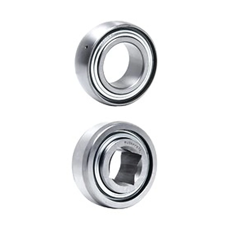

Triple-Lip Seal Farm Implement Bearings is a agricultural bearing inserts with enhanced sealing using agricultural bearing construction with contamination-focused sealing/service options; this version uses series-specific shaft retention. For fit approval, check bore form, seal arrangement and implement seating geometry.
Before dismantling the support, capture the as-installed condition. Measure the shaft centre above the mounting face, record the fixing-hole locations, and photograph any spacers or non-standard hardware. If the base has been welded, slotted or repaired, treat those dimensions as the current machine reality. An old equipment manual can still be helpful, but it should not overrule what is physically present on the machine today.
MOQ: 50 pcs. Minimum order value USD 1,500; mixed orders and trial quantities welcome.
Triple-Lip Seal Farm Implement Bearings are agricultural bearing inserts with enhanced sealing using agricultural bearing construction with contamination-focused sealing/service options. Available in round bore and square bore configurations across multiple series. For fit approval, check bore form, seal arrangement and implement seating geometry.
The surrounding use case is typically agricultural implements and rotating farm machinery exposed to soil, moisture and seasonal service, but the final choice still depends on the actual machine position and service conditions.
Replacement work on an older machine is rarely as simple as reading the code on the bearing housing. The useful question is whether the new unit will occupy the same physical relationship to the shaft and frame after years of repairs, shimming or local modifications.
Before dismantling the support, capture the as-installed condition. Measure the shaft centre above the mounting face, record the fixing-hole locations, and photograph any spacers or non-standard hardware. If the base has been welded, slotted or repaired, treat those dimensions as the current machine reality. An old equipment manual can still be helpful, but it should not overrule what is physically present on the machine today.
Keep the removed unit until the replacement has been checked. The old part can reveal details that a worn label does not: which side maintenance staff approached, where the locking hardware sat, whether a cover was used, and how much clearance existed around the housing. Those clues are especially valuable when two candidate products share the same bore yet use a different footprint or shaft-retention method.
For purchasing, the best record is a short package containing the complete old code, the measured interface, and one wider photo of the installation. This reduces the chance of ordering a visually similar unit that only fails when the shutdown is already underway. Once a replacement fits successfully, update the spare-parts record with the confirmed dimensions rather than keeping an uncertain legacy description.
| Bearing No. | Type | Bearing Bore Size A | Outside Dia. B | Inner Ring Width | Outer Ring Width | ||||
|---|---|---|---|---|---|---|---|---|---|
| (in.) | (mm) | (in.) | (mm) | (in.) | (mm) | (in.) | (mm) | ||
| 205PPB7 | 1 | 0.9375 | 23.813 | 2.0472 | 52 | 1.3748 | 34.92 | 0.591 | 15 |
| W208PPB7 | 1 | 1.1880 | 30.175 | 3.1496 | 80 | 1.189 | 30.2 | 0.709 | 18 |
| W208PP10 | 4 | 1.5005 | 38.113 | 3.1496 | 80 | 1.691 | 42.96 | 0.827 | 21 |
| W208PPB23 | 1 | 1.5005 | 38.113 | 3.1496 | 80 | 1.691 | 42.96 | 1.189 | 30.2 |
| W209PPB2 | 2 | 1.7717 | 45 | 3.3460 | 85 | 1.189 | 30.2 | 1.189 | 30.2 |
| W209PPB4 | 2 | 1.5350 | 39 | 3.3460 | 85 | 1.189 | 30.2 | 1.189 | 30.2 |
| W210PP2 | 5 | 1.9380 | 49.225 | 3.5433 | 90 | 1.189 | 30.2 | 1.189 | 30.2 |
| W210PPB2 | 2 | 1.9380 | 49.225 | 3.5433 | 90 | 1.189 | 30.2 | 1.189 | 30.2 |
| W211PP2 | 5 | 2.1880 | 55.575 | 3.9370 | 100 | 1.313 | 33.34 | 1.313 | 33.34 |
| W211PPB2 | 2 | 2.1880 | 55.575 | 3.9370 | 100 | 1.313 | 33.34 | 1.313 | 33.34 |
| Bearing No. | Type | Square Shaft Size (in.) | Square Bore Size (mm) | Outside Dia. B | Inner Ring Width | Outer Ring Width | |||
|---|---|---|---|---|---|---|---|---|---|
| (in.) | (mm) | (in.) | (mm) | (in.) | (mm) | ||||
| W208PPB13 | 1 | 7/8 | 23.117 | 3.1496 | 80 | 1.437 | 36.5 | 0.709 | 18 |
| W208PPB6 | 1 | 1 | 26.162 | 3.1496 | 80 | 1.437 | 36.5 | 0.709 | 18 |
| W208PP5 | 4 | 1-1/8 | 29.972 | 3.1496 | 80 | 1.437 | 36.5 | 0.709 | 18 |
| W208PPB5 | 1 | 1-1/8 | 29.972 | 3.1496 | 80 | 1.437 | 36.5 | 0.709 | 18 |
| W208PP8 | 4 | 1-1/8 | 29.972 | 3.1496 | 80 | 1.437 | 36.5 | 1.189 | 30.2 |
| W208PPB8 | 1 | 1-1/8 | 29.972 | 3.1496 | 80 | 1.437 | 36.5 | 1.189 | 30.2 |
| W208PPB11 | 3 | 7/8 | 23.117 | 3.3760 | 85.75 | 1.437 | 36.5 | 1.189 | 30.2 |
| W208PPB12 | 3 | 1-1/8 | 29.972 | 3.3760 | 85.75 | 1.437 | 36.5 | 1.189 | 30.2 |
| W209PPB5 | 1 | 1-1/4 | 32.766 | 3.3460 | 85 | 1.437 | 36.5 | 1.189 | 30.2 |
| W210PP4 | 5 | 1-1/8 | 29.972 | 3.5433 | 90 | 1.189 | 30.2 | 1.189 | 30.2 |
| W210PPB4 | 2 | 1-1/8 | 29.972 | 3.5433 | 90 | 1.189 | 30.2 | 1.189 | 30.2 |
| W211PP3 | 5 | 1-1/2 | 38.89 | 3.9370 | 100 | 1.313 | 33.34 | 1.313 | 33.34 |
| W211PPB3 | 2 | 1-1/2 | 38.89 | 3.9370 | 100 | 1.313 | 33.34 | 1.313 | 33.34 |
| W211PP5 | 4 | 1-1/2 | 38.89 | 4.0000 | 101.6 | 1.750 | 44.45 | 1.438 | 36.52 |
| W211PPB6 | 3 | 1-1/2 | 38.89 | 4.0772 | 103.56 | 1.750 | 44.45 | 1.438 | 36.52 |
Use the drawing to compare bore form, seal arrangement and implement seating geometry. Read the printed values rather than scaling the illustration; for modified equipment, send current machine measurements with the enquiry. For square bore models, confirm the shaft key size matches the bore size listed — the suffix number in the part number is not always a direct shaft-size indicator.
Round bore models (205PPB7 through W211PPB2) suit standard round-shaft implement positions. Square bore variants support keyed square shafts common on North American disc harrows and planters. Match bore form and sealing level to the implement shaft and contamination exposure.
For material handling, the Type 1–5 arrangement changes installation access and shaft retention. Confirm the seating geometry matches the housing before standardising the spare across the line.
In tillage and seedbed equipment, the triple-lip seal design provides a layered contamination barrier against soil ingress and seasonal moisture. Use only where the actual moisture, contamination and cleaning conditions match the selected product family.
Compare mounting style, shaft locking, bore range and installation envelope before selecting the alternative.
Send the old code, measured interface and an installation photo for FARM-TRIPLE-LIP. For square bore models, include the shaft key width and depth alongside the bore size measurement.
Triple-Lip Seal Farm Implement Bearings is a agricultural bearing inserts with enhanced sealing using agricultural bearing construction with contamination-focused sealing/service options; this version uses series-specific shaft retention. For fit approval, check bore form, seal arrangement and implement seating geometry.
Before dismantling the support, capture the as-installed condition. Measure the shaft centre above the mounting face, record the fixing-hole locations, and photograph any spacers or non-standard hardware. If the base has been welded, slotted or repaired, treat those dimensions as the current machine reality. An old equipment manual can still be helpful, but it should not overrule what is physically present on the machine today.
MOQ: 50 pcs. Minimum order value USD 1,500; mixed orders and trial quantities welcome.